


NX-800/800H
49
Test Equipment Required for Alignment
Test Equipment Major Specifi cations
1. Standard Signal Generator
(SSG)
Frequency Range 400 to 520MHz
Modulation Frequency modulation and external modulation
Output –127dBm/0.1µV to greater than –20dBm/22.4mV
When performing the Frequency adjustment, the following accuracy is necessary.
• 0.001ppm
Use a standard oscillator for adjustments, if necessary.
2. Power Meter
Input Impedance 50
Ω
Operation Frequency 400 to 520MHz
Measurement Capability Vicinity of 100W
3. Deviation Meter Frequency Range 400 to 520MHz
4. Digital Volt Meter (DVM)
Measuring Range 10mV to 20V DC
Input Impedance High input impedance for minimum circuit loading
5. Oscilloscope DC through 30MHz
6. High Sensitivity
Frequency Counter
Frequency Range 10Hz to 1000MHz
Frequency Stability 0.01ppm or less
7. Ammeter 20A or more
8. AF Volt Meter (AF VTVM)
Frequency Range 50Hz to 10kHz
Voltage Range 1mV to 10V
9. Audio Generator (AG)
Frequency Range 50Hz to 5kHz or more
Output 0 to 1V
10. Distortion Meter
Capability 3% or less at 1kHz
Input Level 50mV to 10Vrms
11. 4
Ω
Dummy Load Approx. 4
Ω
, 20W
12. Regulated Power Supply
13.6V, approx. 20A (adjustable from 9V to 20V)
Useful if ammeter equipped
13. Spectrum Analyzer
Frequency Range 40MHz to 520MHz
Input Level Up to +20dBm
Input Sensitivity –100dBm
Resolution Bandwidth 100Hz
Video Bandwidth 100Hz
14. Tracking Generator
Frequency Range 40MHz to 520MHz
Output Level –30dBm to 0dBm
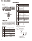
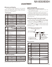
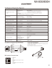
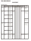
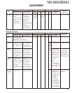
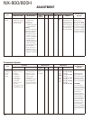
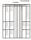
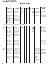
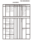
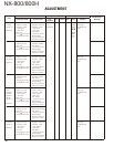
ADJUSTMENT
1
8
1 : BLC/AFO
2 : +B
3 : GND
4 : PTT/TXD (PC serial data from radio)
5 : MICE
6 : MIC
7 : HOOK/RXD (PC serial data to radio)
8 : DM/KVL
MIC connector (Front panel view)
Test cable for microphone input (E30-3360-08)
3
2
4
5
6
7
8
3
1
2
4
5
6
7
8
1
GREEN
RED
BLACK
BLUE
SHIELD
WHITE
GRAY
YELLOW
PTT
E
MIC-E
MIC
HK
Lead wire +
MIC
Shield wire –
Tuning cable (E30-3383-05)
Adapter cable (E30-3383-05) is required for injecting an au-
dio if PC tuning is used.
See “PC Mode” section fot the connection.