


NX-800/800H
9
3.
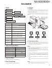
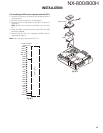
Control Head Remote Kit (KRK-10: Option)
The KRK-10 remote kit is used to remotely operate the
transceiver.
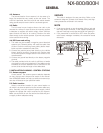
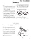
3-1. Installing the KRK-10 kit to the transceiver
1. Remove the front panel from the transceiver.
2. Install the KRK-10 main panel onto the transceiver.
3. Install the KRK-10 rear panel onto the front panel.
4. Connect the KRK-10 main panel to the rear panel with
the cable.
■
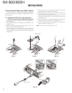
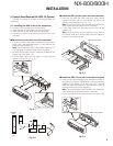
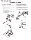
Remove the front panel from the transceiver
1. Lift the two tabs of the panel on the bottom of the trans-
ceiver with a fl at-head screwdriver (
q
) and remove the
panel from the chassis (
w
).
Note: Confi rm that the tabs of the speaker hardware fi x-
ture and holder is securely fi tted in the front panel.
2. Remove the fl at cable from the connector (CN901) of the
display unit of the panel. (
e
)
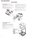
3. Fold the black line of the flat cable (in three parts) as
shown in Figure 3-2. (
r
,
t
,
y
)
CN901
:
@
.
Fig. 3-1
B
;
=
Chassis
side
Panel
side
Fig. 3-2
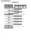
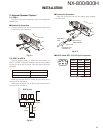
■
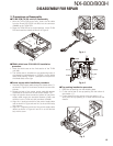
Install the KRK-10 main panel onto the transceiver
4. Insert the fl at cable that was removed in step 2 above
into the connector (CN1) of the interface unit (A/2) of the
KRK-10 main panel (A62-1101-11). (
u
)
Note: The terminal side of the fl at cable must face down
when inserting the fl at cable into the connector.
5. Fit the main panel with four tabs onto the front of the
chassis. (
i
)
Note: When installing the main panel onto the front of
the chassis, hold down the fl at cable with your fi ngers to
prevent it from being caught.
CN1
KRK-10 main panel
>
2
Fig. 3-3
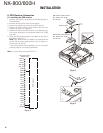
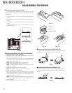
■
Install the KRK-10 rear panel onto the front panel
6. Insert the fl at cable attached to the interface unit (A/2) of
the KRK-10 rear panel (A82-0056-21) into the connector
(CN901) of the display unit of the panel (
o
). (The fl at
cable has been pre-inserted in the connector (CN2) of
the rear panel at the time of shipping.)
Note: The terminal side of the fl at cable must face down
when inserting the fl at cable into the connector.
7. Fit the four tabs of the rear panel into the front panel. (
!0
)
CN901
CN2
KRK-10 rear panel
8
Fig. 3-4
INSTALLATION
;
=
B