


NX-800/800H
64
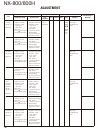
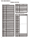
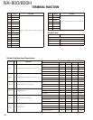
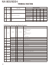
Pin No.
Name Function
4 AUXIO9
Refer to “D-sub 25-pin connector specifi ca-
tion”.
5DI
6 MI2
7 GND
8 AUXIO8
9 TXD2
10 RXD2
11 GND
12 AUXIO7
13 AUXIO6
14 SB
15 AUXO2
16 AUXO1
17 AFO
18 GND
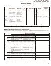
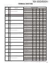
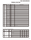
Pin No.
Name Function
19 DEO
Refer to “D-sub 25-pin connector specifi ca-
tion”.
20 AUXIO5
21 AUXIO4
22 AUXIO3
23 AUXIO2
24 AUXIO1
25 ME
Solder Land
Name Description
to GPS receiver
DGND Ground
RXD2 Data input
5V_2 5V power supply
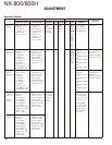
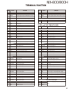
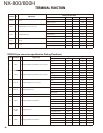
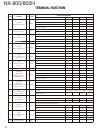
TERMINAL FUNCTION
Solder Pad Interface Description
Pin Name I/O SignalType
Rating and Condition
Parameter Min Typ Max Unit
OPT1 I/O Digital/CMOS Out/CMOS In with Interrupt
VIH 2.7 - 3.5 V
VIL –0.3 - 0.7 V
VOH (Io=–2mA) 2.8 - 3.4 V
VOL (Io=2mA) - - 0.7 V
OPT3 I/O Digital/CMOS Out/CMOS In with Interrupt
VIH 2.7 - 3.5 V
VIL –0.3 - 0.7 V
VOH (Io=–2mA) 2.8 - 3.4 V
VOL (Io=2mA) - - 0.7 V
26P_RD I Digital/CMOS In with Interruput
VIH 2.7 - 3.5 V
VIL –0.3 - 0.7 V
Baud Rate - - 19200 bps
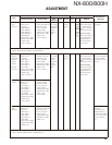
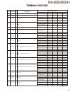
26P_TD O Digital/CMOS Out
VOH (Io=–2mA) 2.8 - 3.4 V
VOL (Io=2mA) - - 0.7 V
Baud Rate - - 19200 bps
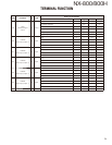
OPT4 I/O Digital/CMOS Out/CMOS In
VIH 2.7 - 3.5 V
VIL –0.3 - 0.7 V
VOH (Io=–2mA) 2.8 - 3.4 V
VOL (Io=2mA) - - 0.7 V
OPT10
(USEL)
O Digital/Analog
Output Amplitude - 0.28 - Vp-p
Coupling Capacitor 0.1 uF
Allowable Load 100 - - k
Ω
Pull Down Registor - 470 - k
Ω