


NX-800/800H
15
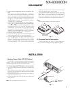
DISASSEMBLY FOR REPAIR
2. Precautions on Reassembly
■
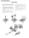
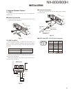
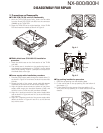
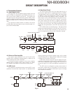
TX-RX PCB (TX-RX unit A/2) Reassembly
1. With the TX-RX PCB turned over, insert the flat cable
from the D-sub PCB (TX-RX unit B/2) into the connector
(CN600) on the TX-RX PCB.
2. Place the TX-RX PCB at its original position, tilt the TX-RX
PCB and install the chassis as shown in Figure 3.
Fig. 3
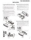
■
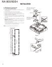
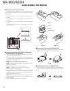
FINAL shield case (F10-2489-13) installation
procedure
1. Place the shield case on the fi nal section of the TX-RX
unit (A/2).
2. The shield case is installed on the positioning boss of
the chassis by pushing down on “PUSH2” (on the shield
case) while pushing “PUSH1” (stamped on two parts on
the shield case) to the right.
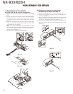
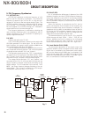
■
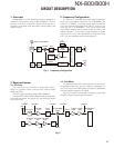
Power supply cable installation procedure
1. Pass the power supply cable through the chassis hole (
q
)
as shown in Figure 4-1 and insert the bush into the chas-
sis hole.
2. Rotate the bush of the power supply cable 90 degrees
clockwise as viewed from the rear of the chassis. (
w
)
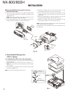
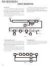
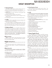
3. Align the ignition sense connector (yellow) of the power
supply cable around the chemical capacitor (C401) and
connect it to the TX-RX unit (A/2) connector (CN403).
4. Align the + (positive) terminal of the power supply cable
(red) as shown in Figure 4-2 and fi x it to the terminal strip
with a screw.
5. Align the – (negative) terminal of the power supply cable
(black) as shown in Figure 4-2 and fi x it to the terminal
strip with a screw.
@
:
Fig. 4-1
IC403
C401
IC715
CN403
Black
Red
Fig. 4-2
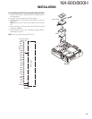
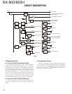
■
Top packing installation procedure
1. Place the top packing over the shielding plate.
2. Fit the convex tab of the top packing into the hollow of
the chassis. (
q
)
3. Fit the chassis into the groove of the top packing. (
w
)
Verify that the top packing is in close contact with the
chassis.
:
@
Fig. 5