


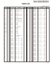
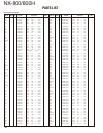
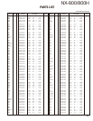
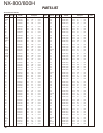

NX-800/800H
41
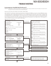
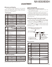
Fault diagnosis of the BGA (Ball Grid Array) IC
Overview: A fl owchart for determining whether or not the transceiver can be powered on (the LCD does not function even if
the power switch is turned on) due to broken BGA parts.
BGA parts: ASIC (IC510), DSP (IC502), FLASH (IC501), SRAM (IC503)
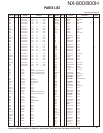
When the BGA IC is problematic, please bring the printed circuit board (X57-7390-XX) in for service. Various ESN/default adjust-
ment values are written on the printed circuit board for service. Additionally various ESN stickers are included. The power mod-
ule (RA30H4452M123: K, RA55H4452M123: HK), short connector (E37-1180-05) and button type lithium battery (W09-0971-05)
do not belong to the printed circuit board for service. Please use the part which has been attached to the printed circuit board.
After the printed circuit board has been readjusted, please attach any ESN stickers to the chassis. When “ESN Validation” is
used with NXDN Trunking, you must modify the ESN register.
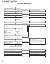
● Checking power supply voltage
Checking voltage
Points to be checked Normal voltage
33M IC402 (5 pin) 3.3V
15M IC409 (5 pin) 1.5V
33A IC408 (5 pin) 3.3V
33BU D411 (Cathode side) 3.3V
Power supply of each device is connected through the coil.
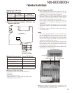
[ASIC]
33M: L903, 15M: L511, 33A: R603
[DSP]
33M: L503, 15M: L502
[FLASH]
33M: L501
[SRAM]
33BU: L522
● Checking the clock
Checking the clock
Points to be checked Normal voltage (3.3V)
18.432MHz ASIC side R569 18.432MHz
DSP side R511 18.432MHz
32.768kHz IC504 (1 pin) or R545 32.768kHz
When a normal
value is confirmed.
When a normal
value is confirmed.
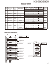
● Checking the Reset/Control signal
Checking the control signal input to the ASIC
Points to be checked Normal voltage
RST (RESET) IC506 (4 pin) 3.3V
/BINT IC401 (1 pin) 3.3V
/OVRB D403 (Cathode side) 3.3V
Checking the ASIC input switch signal
*Each signal is not masked by the setting of the FPU.
The POWER key is pressed and held.
Points to be checked Confirmed voltage
/PSW (R619) 0V
The ignition key is kept ON.
Points to be checked Confirmed voltage
/IGN (R618) 0V
Remove the R569, R511 and R545. If it oscillates
normally, the DSP and ASIC may be broken.
The BGA parts are not broken.
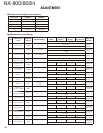
Checking for an abnormal point
33M has an abnormal voltage.
[ASIC]
Remove L508 to check the voltage of the 33M.
If the voltage becomes normal, the ASIC is broken.
[DSP]
Remove L503 to check the voltage of the 33M.
If the voltage becomes normal, the DSP is broken.
[FLASH]
Remove L501 to check the voltage of the 33M.
If the voltage becomes normal, the FLASH is broken.
15M has an abnormal voltage.
[ASIC]
Remove L511 to check the voltage of the 15M.
If the voltage becomes normal, the ASIC is broken.
[DSP]
Remove L502 to check the voltage of the 15M.
If the voltage becomes normal, the DSP is broken.
33A has an abnormal voltage.
[ASIC]
Remove R603 to check the voltage of the 33A.
If the voltage becomes normal, the ASIC is broken.
33BU has an abnormal voltage.
[SRAM]
Remove L522 to check the voltage of the 33BU.
If the voltage becomes normal, the SRAM is broken.
If the voltage is not corrected, there is a problem
other than the BGA parts.
When an abnormal
value is confirmed.
When an abnormal
value is confirmed.
When an abnormal
value is confirmed.
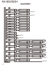
● Checking the output signal
from the ASIC
Points to be checked Normal voltage
/FRST R509 3.3V
If the /FRST is always 0V, the ASIC is broken.
If the /FRST repeats 3.3V and 0V at intervals,
the ASIC, FLASH and SRAM may be broken.
When an abnormal
value is confirmed.
When an abnormal
value is confirmed.
When a normal
value is confirmed.
When a normal
value is confirmed.
When a normal
value is confirmed.
TROUBLE SHOOTING