


NX-800/800H
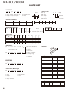
22
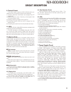
8. Signaling Circuit
8-1. Encode (QT/DQT/DTMF/MSK/2TONE)
Each signaling data signal of QT, DQT, DTMF and MSK is
generated by the DSP circuit, superposed on a modulation
signal and output from IC510. The modulation balance of
the QT/DQT signal is adjusted by the D/A converter (IC712)
and the resulting signal is routed to the modulation input of
the VCO and VCTCXO (X1). The each deviation of the TX
QT, DQT, DTMF and MSK tone is adjusted by changing the
output level of the IC510 and the resulting signal is routed
to VCO and VCXO. The RX DTMF tone is routed to the re-
ceive audio signal system, and is output from the speaker.
8-2. Decode (QT/DQT/DTMF/2TONE/MSK)
The audio signal is removed from the FM detection
signal sent to the DSP circuit and the resulting signal is de-
coded.
9. Compander Circuit
The term “compander” means compressor and expand-
er. The compander reduces noise by utilizing a compressor
and an expander. The NX-800/800H contains DSP (IC502) to
perform this operation. The NX-800/800H compander can
be turned on or off using the FPU.
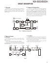
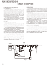
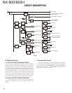
CIRCUIT DESCRIPTION
D401
DET
Q401
INV
IC402
AVR
IC403
AVR
Q407
80T SW
Q408
80R SW
IC410
DC/DC
IC404
AVR
Q409
50R SW
Q404
SB SW
Q412
50MC SW
IC401
DET
IC405
DC/DC
50MC
SBC
CN405
RS-232C Driver
IC408
AVR
33A
33A-2
ASIC (Analog)
33M
ASIC, DSP I/O
Flash memory
+B
+B
SB
80C
80R
80T
TXC
/OVRB
/BINT
RXC
SBC
RXC
150C
50C
50R
Final Amp
Audio Amp, Display Block
PA connector
SB
D_Sub 25Pin connector
Internal Option
Display Block
TX circuit
RX circuit
Assist, Tune circuit
VCO, Internal Option,
I/O expander, FM IC
IC409
AVR
Q411
33BU SW
IC506
DET
33BU
15M
ASIC, DSP core
SRAM, RTC
MCU Reset
Q416
SW
Audio circuit
RX circuit
IC406
AVR
33C
TCXO, PLL
IC407
AVR
33GPS
Internal Option
F401
5A
F501
2A
Fig. 8