


NX-800/800H
3
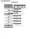
4-2. Antenna
The favored location for an antenna is in the center of a
large, flat conductive area, usually at the roof center. The
trunk lid is preferred, bond the trunk lid and vehicle chassis
using ground straps to ensure the lid is at chassis ground.
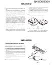
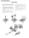
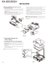
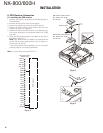
4-3. Radio
The universal mount bracket allows the radio to be
mounted in a variety of ways. Be sure the mounting surface
is adequate to support the radio’s weight. Allow suffi cient
space around the radio for air cooling. Position the radio
close enough to the vehicle operator to permit easy access
to the controls when driving.
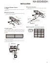
4-4. DC Power and wiring
1. This radio may be installed in negative ground electrical
systems only. Reverse polarity will cause the cable fuse
to blow. Check the vehicle ground polarity before instal-
lation to prevent wasted time and effort.
2. Connect the positive power lead directly to the vehicle
battery positive terminal. Connecting the Positive lead
to any other positive voltage source in the vehicle is not
recommended.
3. Connect the ground lead directly to the battery negative
terminal.
4. The cable provided with the radio is suffi cient to handle
the maximum radio current demand. If the cable must be
extended, be sure the additional wire is suffi cient for the
current to be carried and length of the added lead.
5. INSTALLATION PLANNING – CONTROL STATIONS
5-1. Antenna system
Control station. The antenna system selection depends
on many factors and is beyond the scope of this manual.
Your KENWOOD dealer can help you select an antenna sys-
tem that will best serve your particular needs.
5-2. Radio location
Select a convenient location for your control station ra-
dio which is as close as practical to the antenna cable entry
point. Secondly, use your system’s power supply (which
supplies the voltage and current required for your system).
Make sure suffi cient air can fl ow around the radio and pow-
er supply to allow adequate cooling.
SERVICE
This radio is designed for easy servicing. Refer to the
schematic diagrams, printed circuit board views, and align-
ment procedures contained in this manual.
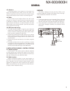
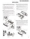
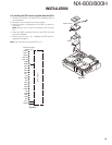
NOTE
• If you do not intend to use the speaker 3.5-mm jack and
the D-sub 25-pin connector, fi t the supplied speaker-jack
cap and D-sub cap to stop dust and sand from getting in.
• If the transceiver is turned ON or OFF when the power-
on/off status message is enabled, the transceiver sends
the status.
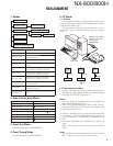
Speaker
jack cap
D-sub
cap
Power input
connector
Ignition
sense cable
Antenna
connector
GENERAL