


NX-800/800H
63
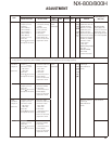
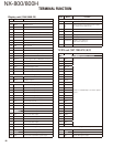
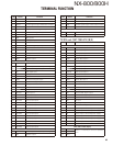
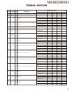
Pin No.
Name Function
5 NC No connection
6 50C 5V output.
7 SHIFT Control signal output of Beat-shift function
8~11 GND Ground
12 /PRST Display MCU reset signal output
13 AFO RX fi ltered AF signal output
14 GND Ground
15 ME MIC ground
16 MIC MIC signal input
17,18 GND Ground
19 /PSW Detection signal input of power switch
20 NC No connection
21,22 SB Power output of switched power supply
23 80C 8V output
24 GND Ground
25~30 SPO Speaker output
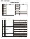
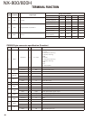
CN600 (to TX-RX unit B/2 CN901)
1 NC No connection.
2~7 SB Power output of switched power supply.
8 AFO RX fi ltered AF signal output.
9 DI Data signal input.
10 50C 5V output.
11 GND Ground.
12 DEO RX Detected signal output.
13 MI2 External MIC signal input.
14 ME MIC ground.
15 GND Ground.
16 RXD0 Serial data input 0.
17 AUXO2 AUX output 2.
18 TXD0 Serial data output 0.
19 AUXO1 AUX output 1.
20 AUXIO9 AUX input/output 9.
21 AUXIO5 AUX input/output 5.
22 AUXIO8 AUX input/output 8.
23 AUXIO4 AUX input/output 4.
24 TXD2 Serial data output 2.
25 AUXIO3 AUX input/output 3.
26 RXD2 Serial data input 2.
27 AUXIO2 AUX input/output 2.
28 AUXIO1 AUX input/output 1.
29 AUXIO7 AUX input/output 7.
30 AUXIO6 AUX input/output 6.
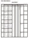
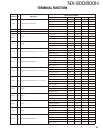
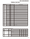
CN705
1 SB Power output of switched power supply.
2 SPI Speaker output.
Pin No.
Name Function
3 SPO Speaker input.
4 PA Control signal output of PA function.
5 HOR Control signal output of Horn alert function.
6 GND Ground.
CN403
1 IGN Ignition sense input.
2 GND Ground.
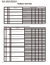
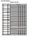
TX-RX unit (X57-7390-XX) (B/2)
Pin No.
Name Function
CN901 (to TX-RX unit A/2 CN600)
1 AUXIO6 AUX input/output 6.
2 AUXIO7 AUX input/output 7.
3 AUXIO1 AUX input/output 1.
4 AUXIO2 AUX input/output 2.
5 RXD2 Serial data output 2.
6 AUXIO3 AUX input/output 3.
7 TXD2 Serial data input 2.
8 AUXIO4 AUX input/output 4.
9 AUXIO8 AUX input/output 8.
10 AUXIO5 AUX input/output 5.
11 AUXIO9 AUX input/output 9.
12 AUXO1 AUX input 1.
13 TXD0 Serial data input 0.
14 AUXO2 AUX input 2.
15 RXD0 Serial data output 0.
16 GND Ground.
17 ME MIC ground.
18 MI2 External MIC signal output.
19 DEO RX Detected signal input.
20 GND Ground.
21 50C 5V input.
22 DI Data signal output.
23 AFO RX fi ltered AF signal input.
24 SB Power input of switched power supply.
25 SB Power input of switched power supply.
26 SB Power input of switched power supply.
27 SB Power input of switched power supply.
28 SB Power input of switched power supply.
29 SB Power input of switched power supply.
30 NC No connection.
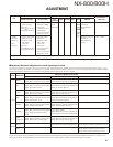
J901 (ACC. D-Sub 25pin)
1NC
Refer to “D-sub 25-pin connector specifi ca-
tion”.
2 RXD1
3 TXD1
TERMINAL FUNCTION