


70
13 CONNECTING PERIPHERAL EQUIPMENT
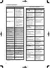
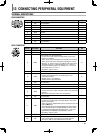
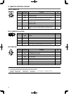
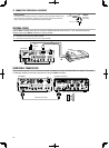
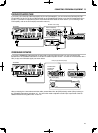
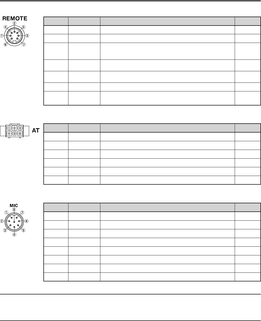
REMOTE CONNECTOR
Pin No. Pin Name Function I/O
1 SPO Speaker output O
2 COM Common terminal I/O
3SS
Standby; when grounded, the transceiver enters TX mode.
• During transmission, the audio input of ACC2 connector
terminal 11 (ANI) and the USB terminal are muted.
I
4 MKE
When connected with the common terminal, the amplifi er
enters TX mode.
I/O
5 BRK
When connected with the common terminal, the amplifi er
enters RX mode.
I/O
6 ALC ALC input from the amplifi er (approx. -7 V). I
7RL
Approx. +12 V DC is output when in TX mode (10 mA
max.).
O
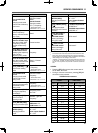
EXT.AT CONNECTOR (for AT-300)
Pin No. Pin Name Function I/O
1 GND Ground
—
2 TT AT-300 control input/ output I/O
3 GND Ground
—
4 NC No connection
—
5 TS AT-300 control input/ output I/O
6 14S Power supply for EXT.AT Switched 13.8 V (4 A max.). O
MIC CONNECTOR
Pin No. Pin Name Function I/O
1 MIC MIC signal input I
2 SS MIC standby (PTT) control I
3 MD MIC Down control I
4 MU MIC UP control I
5 8A Switched 8 V (10 mA max.) O
6 NC No connection
—
7 MSG MIC GND
—
8 MCG GND
—
Note:
◆ The terminal pin numbers are arranged as seen on the front and rear panel.
◆ Do not use a cable exceeding 3 m (9.8 feet) with the following connectors:
PHONES jack MIC connector COM connector EXT. SP jack ACC 2 connector REMOTE connector
KEY jack PADDLE jack DRV connector USB connector