


3 - 62
3. SIGNALS AND WIRING
3.13 Power line circuit of the MR-J2S-11KA to MR-J2S-22KA
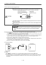
CAUTION
When the servo amplifier has become faulty, switch power off on the amplifier
power side. Continuous flow of a large current may cause a fire.
Use the trouble (ALM) to switch power off. Otherwise, a regenerative brake
transistor fault or the like may overheat the regenerative brake resistor, causing a
fire.
POINT
The power-on sequence is the same as in Section 5.7.3.
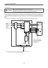
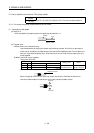
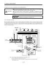
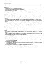
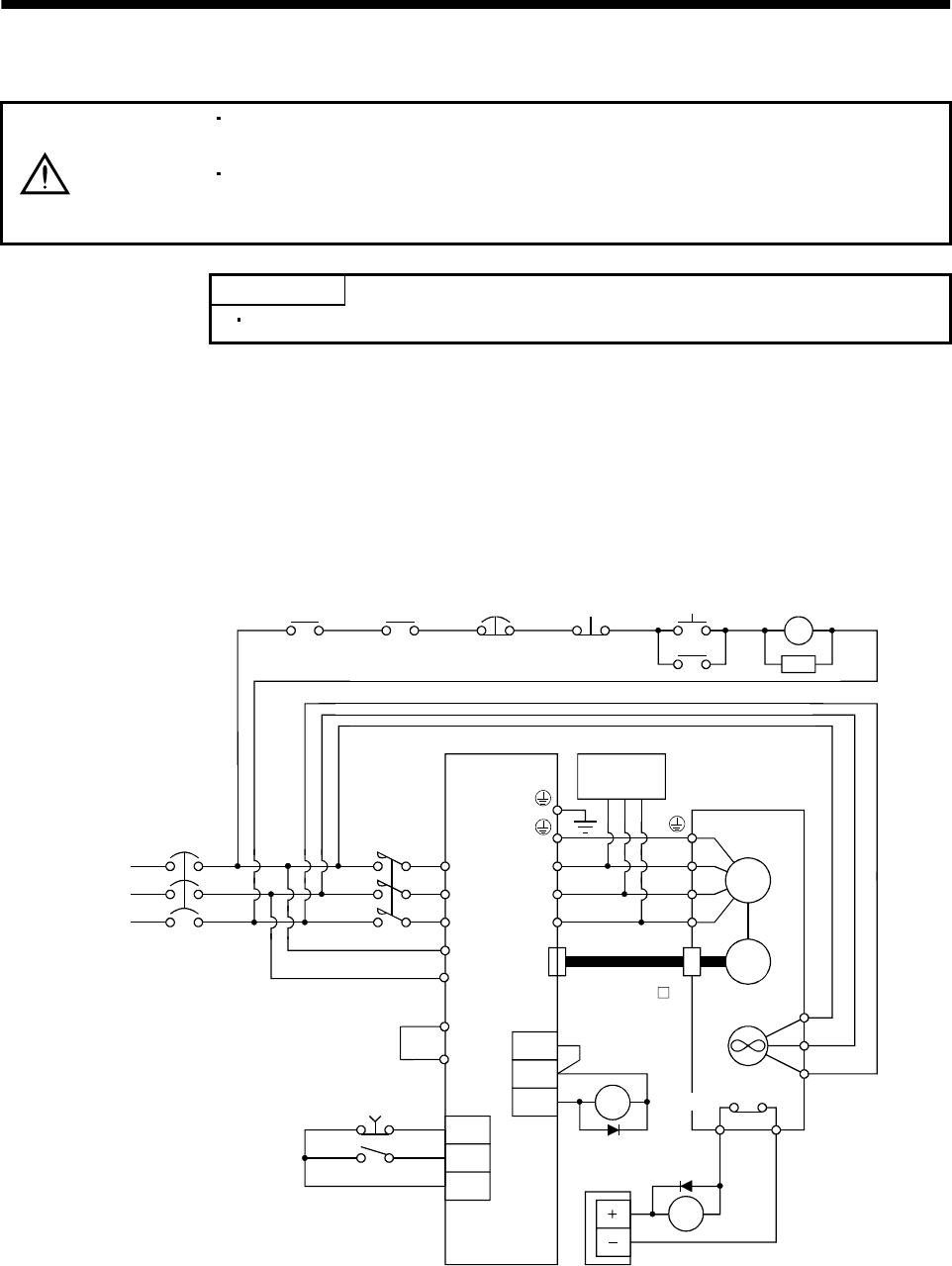
3.13.1 Connection example
Wire the power supply/main circuit as shown below so that power is shut off and the servo-on signal
turned off as soon as an alarm occurs, a servo emergency stop is made valid, a controller emergency stop,
or a servo motor thermal relay alarm is made valid. A no-fuse breaker (NFB) must be used with the input
cables of the power supply.
L
1
L
2
L
3
L
11
L
21
EMG
SON
SG
CN2
U
V
W
U
V
W
M
BU
RA2
BV
BW
MC
SK
ON
MC
NFB MC
OHS2OHS1
ALM
COM
VDD
RA1
Servo motor
thermal relay
RA2
Alarm
RA1
emergency stop
OFF
3-phase
200 to 230VAC
Servo amplifier
(Note1)
Dynamic
break
Servo motor
HA-LFS series
Encoder
Fan
(Note2
)
Servo motor
thermal relay
24VDC
power supply
Emergency stop
servo-on
MR-JHSCBL M
cable
2. There is no BW when the HA-LFS11K2 is used.
Note 1. When using the external dynamic break, refer to section 13.1.4.
Trouble
3. Always connect P-P
1
. (Factory-wired.) When using the power factor improving DC reactor,
refer to Section 13.2.4
P
P
1
(Note3)