


3 - 51
3. SIGNALS AND WIRING
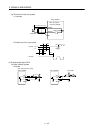
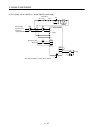
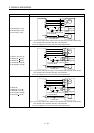
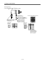
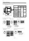
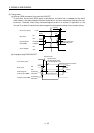
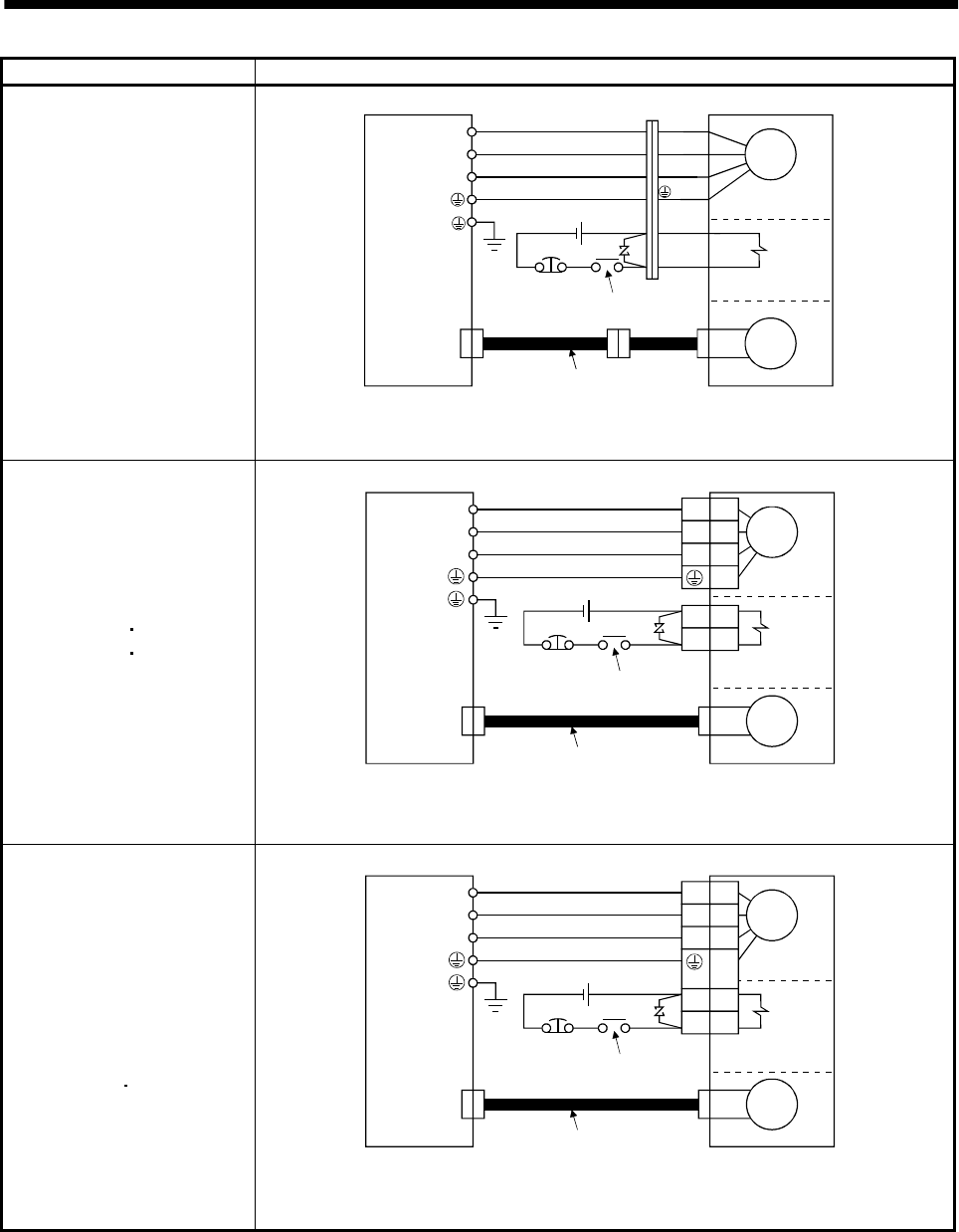
Servo motor Connection diagram
HC-KFS053 (B) to 73 (B)
HC-MFS053 (B) to 73 (B)
HC-UFS13 (B) to 73 (B)
Servo amplifier
(Note 1)
Servo motor
Electromagnetic
brake
24VDC
EMG
(Note 2)
To be shut off when servo-off
or Trouble (ALM)
Encoder cable
CN2
Motor
Encoder
U
V
W
B1
B2
U (Red)
V (White)
W (Black)
(Green)
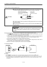
Note 1. To prevent an electric shock, always connect the protective earth (PE) terminal of the
servo amplifier to the protective earth (PE) of the control box.
2. This circuit applies to the servo motor with electromagnetic brake.
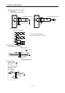
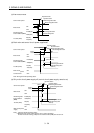
HC-SFS121 (B) to 301 (B)
HC-SFS202 (B)
702 (B)
HC-SFS203 (B)
353 (B)
HC-UFS202 (B) to 502 (B)
HC-RFS353 (B) to 503 (B)
Electromagnetic
brake
(Note 2)
To be shut off when servo-off
or Trouble (ALM)
24VDC
EMG
CN2
U
V
W
U
V
W
B1
B2
Servo amplifier
(Note 1)
Encoder
Encoder cable
Motor
Servo motor
Note 1. To prevent an electric shock, always connect the protective earth (PE) terminal of the
servo amplifier to the protective earth (PE) of the control box.
2. This circuit applies to the servo motor with electromagnetic brake.
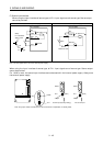
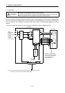
HC-SFS81 (B)
HC-SFS52 (B) to 152 (B)
HC-SFS53 (B) to 153 (B)
HC-RFS103 (B) to 203 (B)
HC-UFS72 (B)
152 (B)
Electromagnetic
brake
(Note 2)
To be shut off when servo-off
or Trouble (ALM)
24VDC
EMG
CN2
U
V
W
U
V
W
B1
B2
Servo amplifier
(Note 1)
Encoder
Encoder cable
Motor
Servo motor
Note 1. To prevent an electric shock, always connect the protective earth (PE) terminal of the
servo amplifier to the protective earth (PE) of the control box.
2. This circuit applies to the servo motor with electromagnetic brake.