


12 - 8
12. CHARACTERISTICS
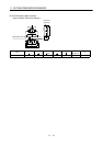
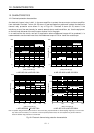
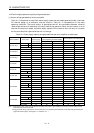
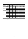
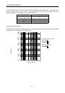
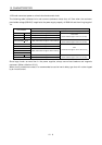
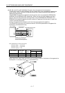
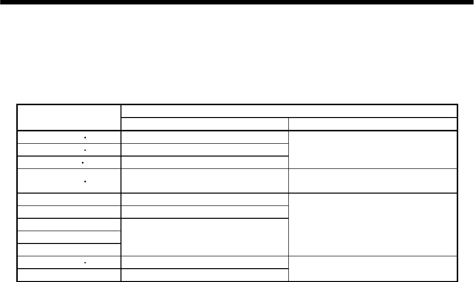
12.5 Inrush currents at power-on of main circuit and control circuit
The following table indicates the inrush currents (reference value) that will flow when the maximum
permissible voltage (253VAC) is applied at the power supply capacity of 2500kVA and the wiring length of
1m.
Inrush Currents (A
0-p
)
Servo Amplifier
Main circuit power supply (L
1
, L
2
, L
3
) Control circuit power supply (L
11
, L
21
)
MR-J2S-10A 20A 30A (Attenuated to approx. 5A in 10ms)
MR-J2S-40A 60A 30A (Attenuated to approx. 5A in 10ms)
MR-J2S-70A 100A 54A (Attenuated to approx. 12A in 10ms)
70 to 100A
(Attenuated to approx. 0A in 0.5 to 1ms)
MR-J2S-200A 350A 120A (Attenuated to approx. 12A in 20ms)
100 to 130A
(Attenuated to approx. 0A in 0.5 to 1ms)
MR-J2S-500A 44A (Attenuated to approx. 20A in 20ms)
MR-J2S-700A 88A (Attenuated to approx. 20A in 20ms)
MR-J2S-11KA
MR-J2S-15KA
MR-J2S-22KA
235A (Attenuated to approx. 20A in 20ms)
30A
(Attenuated to approx. 0A in several ms)
MR-J2S-10A1 20A1 59A (Attenuated to approx. 5A in 4ms)
MR-J2S-40A1 72A (Attenuated to approx. 5A in 4ms)
100 to 130A
(Attenuated to approx. 0A in 0.5 to 1ms)
Since large inrush currents flow in the power supplies, always use no-fuse breakers and magnetic
contactors. (Refer to Section 13.2.2.)
When circuit protectors are used, it is recommended to use the inertia delay type that will not be tripped
by an inrush current.