


2
3.8.2 Connection diagram.........................................................................................................................3-50
3.8.3 I/O terminals ....................................................................................................................................3-52
3.9 Servo motor with electromagnetic brake ............................................................................................. 3-54
3.10 Grounding .............................................................................................................................................3-57
3.11 Servo amplifier terminal block (TE2) wiring method....................................................................... 3-58
3.11.1 For the servo amplifier produced later than Jan. 2006 ............................................................. 3-58
3.11.2 For the servo amplifier produced earlier than Dec. 2005.......................................................... 3-60
3.12 Instructions for the 3M connector....................................................................................................... 3-61
3.13 Power line circuit of the MR-J2S-11KA to MR-J2S-22KA............................................................... 3-62
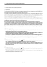
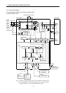
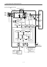
3.13.1 Connection example ...................................................................................................................... 3-62
3.13.2 Servo amplifier terminals .............................................................................................................3-63
3.13.3 Servo motor terminals................................................................................................................... 3-64
4. OPERATION 4- 1 to 4- 6
4.1 When switching power on for the first time.......................................................................................... 4- 1
4.2 Startup...................................................................................................................................................... 4- 2
4.2.1 Selection of control mode.................................................................................................................. 4- 2
4.2.2 Position control mode ....................................................................................................................... 4- 2
4.2.3 Speed control mode........................................................................................................................... 4- 4
4.2.4 Torque control mode......................................................................................................................... 4- 5
4.3 Multidrop communication ...................................................................................................................... 4- 6
5. PARAMETERS 5- 1 to 5- 34
5.1 Parameter list .......................................................................................................................................... 5- 1
5.1.1 Parameter write inhibit ................................................................................................................... 5- 1
5.1.2 Lists.................................................................................................................................................... 5- 2
5.2 Detailed description ............................................................................................................................... 5-26
5.2.1 Electronic gear ................................................................................................................................. 5-26
5.2.2 Analog monitor.................................................................................................................................5-30
5.2.3 Using forward/reverse rotation stroke end to change the stopping pattern.............................. 5-33
5.2.4 Alarm history clear..........................................................................................................................5-33
5.2.5 Position smoothing .......................................................................................................................... 5-34
6. DISPLAY AND OPERATION 6- 1 to 6-16
6.1 Display flowchart..................................................................................................................................... 6- 1
6.2 Status display .......................................................................................................................................... 6- 2
6.2.1 Display examples.............................................................................................................................. 6- 2
6.2.2 Status display list ............................................................................................................................. 6- 3
6.2.3 Changing the status display screen................................................................................................ 6- 4
6.3 Diagnostic mode....................................................................................................................................... 6- 5
6.4 Alarm mode.............................................................................................................................................. 6- 7
6.5 Parameter mode ...................................................................................................................................... 6- 8
6.6 External I/O signal display..................................................................................................................... 6- 9
6.7 Output signal (DO) forced output .........................................................................................................6-12
6.8 Test operation mode ............................................................................................................................... 6-13
6.8.1 Mode change..................................................................................................................................... 6-13
6.8.2 Jog operation.................................................................................................................................... 6-14