


1
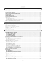
CONTENTS
1. FUNCTIONS AND CONFIGURATION 1- 1 to 1-24
1.1 Introduction.............................................................................................................................................. 1- 1
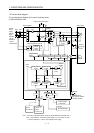
1.2 Function block diagram .......................................................................................................................... 1- 2
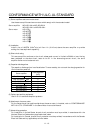
1.3 Servo amplifier standard specifications ................................................................................................ 1- 5
1.4 Function list ............................................................................................................................................. 1- 6
1.5 Model code definition .............................................................................................................................. 1- 7
1.6 Combination with servo motor............................................................................................................... 1- 9
1.7 Structure..................................................................................................................................................1-10
1.7.1 Parts identification.......................................................................................................................... 1-10
1.7.2 Removal and reinstallation of the front cover ..............................................................................1-15
1.8 Servo system with auxiliary equipment............................................................................................... 1-19
2. INSTALLATION 2- 1 to 2- 4
2.1 Environmental conditions....................................................................................................................... 2- 1
2.2 Installation direction and clearances .................................................................................................... 2- 2
2.3 Keep out foreign materials ..................................................................................................................... 2- 3
2.4 Cable stress .............................................................................................................................................. 2- 4
3. SIGNALS AND WIRING 3- 1 to 3- 66
3.1 Standard connection example ................................................................................................................ 3- 2
3.1.1 Position control mode ....................................................................................................................... 3- 2
3.1.2 Speed control mode........................................................................................................................... 3- 6
3.1.3 Torque control mode......................................................................................................................... 3- 8
3.2 Internal connection diagram of servo amplifier .................................................................................. 3-10
3.3 I/O signals................................................................................................................................................ 3-11
3.3.1 Connectors and signal arrangements............................................................................................ 3-11
3.3.2 Signal explanations ......................................................................................................................... 3-15
3.4 Detailed description of the signals........................................................................................................ 3-24
3.4.1 Position control mode ...................................................................................................................... 3-24
3.4.2 Speed control mode..........................................................................................................................3-29
3.4.3 Torque control mode........................................................................................................................ 3-31
3.4.4 Position/speed control change mode ..............................................................................................3-34
3.4.5 Speed/torque control change mode.................................................................................................3-36
3.4.6 Torque/position control change mode ............................................................................................ 3-38
3.5 Alarm occurrence timing chart .............................................................................................................3-39
3.6 Interfaces.................................................................................................................................................3-40
3.6.1 Common line .................................................................................................................................... 3-40
3.6.2 Detailed description of the interfaces ............................................................................................ 3-41
3.7 Input power supply circuit..................................................................................................................... 3-46
3.7.1 Connection example......................................................................................................................... 3-46
3.7.2 Terminals.......................................................................................................................................... 3-48
3.7.3 Power-on sequence...........................................................................................................................3-49
3.8 Connection of servo amplifier and servo motor ...................................................................................3-50
3.8.1 Connection instructions ..................................................................................................................3-50