


4 - 1
4. OPERATION
4. OPERATION
4.1 When switching power on for the first time
Before starting operation, check the following:
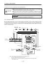
(1) Wiring
(a) A correct power supply is connected to the power input terminals (L
1
, L
2
, L
3
, L
11
, L
21
) of the servo
amplifier.
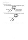
(b) The servo motor power supply terminals (U, V, W) of the servo amplifier match in phase with the
power input terminals (U, V, W) of the servo motor.
(c) The servo motor power supply terminals (U, V, W) of the servo amplifier are not shorted to the
power input terminals (L
1
, L
2
, L
3
)
of the servo motor.
(d) The earth terminal of the servo motor is connected to the PE terminal of the servo amplifier.
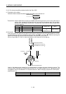
(e) Note the following when using the regenerative brake option, brake unit or power regeneration
converter:
1) For the MR-J2S-350A or less, the lead has been removed from across D-P of the control circuit
terminal block, and twisted cables are used for its wiring.
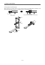
2) For the MR-J2S-500A or more, the lead has been removed from across P-C of the servo amplifier
built-in regenerative brake resistor, and twisted cables are used for its wiring.
(f) When stroke end limit switches are used, LSP and LSN are on during operation.
(g) 24VDC or higher voltages are not applied to the pins of connectors CN1A and CN1B.
(h) SD and SG of connectors CN1A and CN1B are not shorted.
(i) The wiring cables are free from excessive force.
(2) Environment
Signal cables and power cables are not shorted by wire offcuts, metallic dust or the like.
(3) Machine
(a) The screws in the servo motor installation part and shaft-to-machine connection are tight.
(b) The servo motor and the machine connected with the servo motor can be operated.