


5 - 17
5. PARAMETERS
Class No. Symbol Name and function
Initial
value
Unit
Setting
range
Control
mode
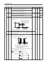
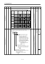
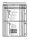
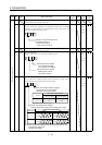
39 VDC Speed differential compensation
Used to set the differential compensation.
Made valid when the proportion control (PC) is switched on.
980 0
to
1000
P
S
40 For manufacturer setting
Do not change this value by any means.
0
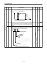
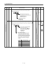
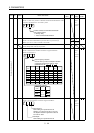
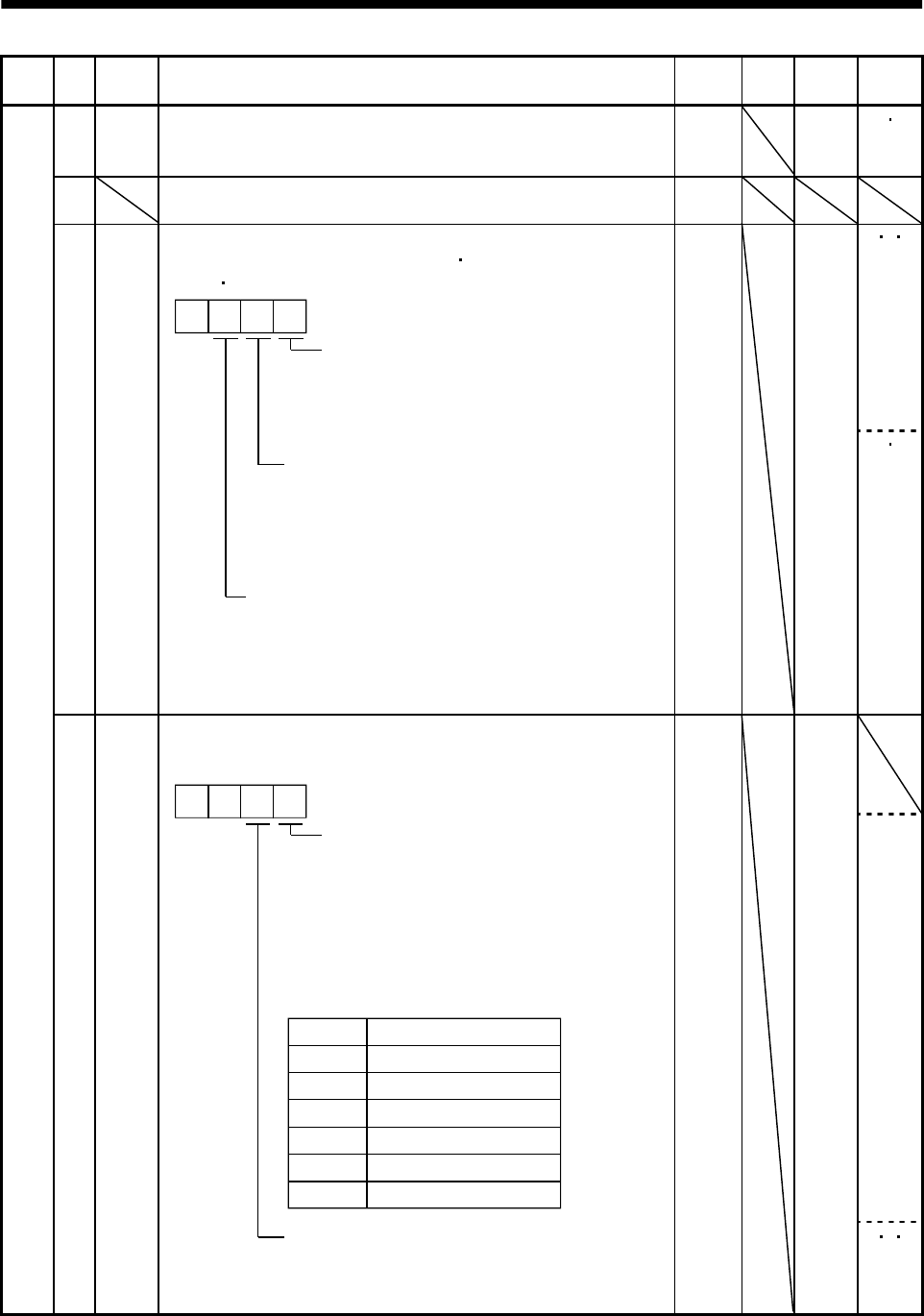
P S T41 *DIA Input signal automatic ON selection
Used to set automatic Servo-on (SON)
forward rotation stroke end
(LSP)
reveres rotation stroke end (LSN)
.
Servo-on (SON) input selection
0: Switched on/off by external input.
1: Switched on automatically in servo
amplifier.
(No need of external wiring)
0: Switched on/off by external input.
1: Switched on automatically in servo
amplifier.
(No need of external wiring)
0: Switched on/off by external input.
1: Switched on automatically in servo
amplifier.
(No need of external wiring)
Reverse rotation stroke end (LSN)
input selection
Forward rotation stroke end
(LSP) input selection
0
0000
Refer to
Name
and
function
column.
P S
P/S
S/T
T/P
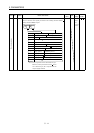
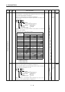
Expansion parameters 1
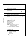
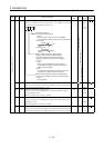
42 *DI1 Input signal selection 1
Used to assign the control mode changing signal input pins and to set
the clear (CR).
Control change (LOP) in-
put pin assignment
Used to set the control mode
change signal input connector
pins. Note that this parameter is
made valid when parameter No.
0 is set to select the position/spe-
ed, speed/torque or torque/posi-
tion change mode.
Set value
0
1
2
Connector pin No.
CN1B-5
CN1B-14
CN1A-8
3CN1B-7
Clear (CR) selection
0: Droop pulses are cleared on the
leading edge.
1: While on, droop pulses are always cleared.
4CN1B-8
5CN1B-9
0 0
0003
Refer to
Name
and
function
column.
P S T