


15 - 48
15. ABSOLUTE POSITION DETECTION SYSTEM
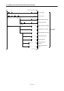
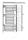
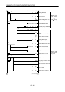
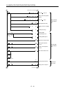
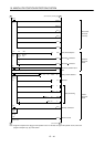
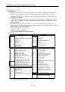
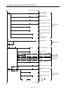
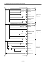
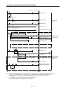
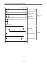
Note 1. For the dog type home position return. Need not be connected for the data set type home position return.
2. If the servo motor provided with the zero point signal is started, the A1SD75 will output the deviation counter clear (CR). Therefore,
do not connect the clear (CR) of the MR-J2-A to the A1SD75 but connect it to the output module of the programmable controller.
3. This circuit is provided for your reference.
4. The electromagnetic brake output should be controlled via a relay connected to the programmable controller output.
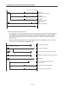
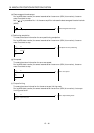
5. Use the differential line driver system for pulse input. Do not use the open collector system.
6. To reinforce noise suppression, connect LG and pulse output COM.