


10 - 10
10. TROUBLESHOOTING
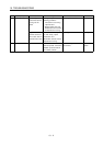
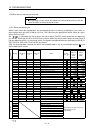
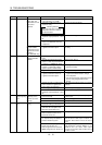
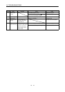
Display Name Definition Cause Action
1. Short occurred in servo amplifier
output phases U, V and W.
Correct the wiring.AL.32 Overcurrent Current that flew is
higher than the
permissible current
of the servo
amplifier.
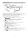
2. Transistor (IPM) of the servo
amplifier faulty.
Checking method
Alarm (AL.32) occurs if power is
switched on after U,V and W
are disconnected.
Change the servo amplifier.
3. Ground fault occurred in servo
amplifier output phases U, V and
W.
Correct the wiring.
4. External noise caused the
overcurrent detection circuit to
misoperate.
Take noise suppression measures.
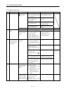
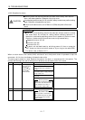
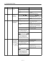
Current higher than
the permissible
current flew in the
regenerative brake
transistor.
(MR-J2S-500A only)
5. Improper wiring of the
regenerative brake option.
Wire the regenerative brake option
correctly.
1. Regenerative brake option is not
used.
Use the regenerative brake option.
2. Though the regenerative brake
option is used, the parameter No.
0 setting is " 00
(not used)".
Make correct setting.
3. Lead of built-in regenerative brake
resistor or regenerative brake
option is open or disconnected.
1. Change lead.
2. Connect correctly.
4. Regenerative transistor faulty. Change servo amplifier
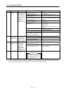
5. Wire breakage of built-in
regenerative brake resistor or
regenerative brake option
1. For wire breakage of built-in
regenerative brake resistor, change
servo amplifier.
2. For wire breakage of regenerative brake
option, change regenerative brake
option.
6. Capacity of built-in regenerative
brake resistor or regenerative
brake option is insufficient.
Add regenerative brake option or increase
capacity.
7. Power supply voltage high. Review the power supply.
AL.33 Overvoltage Converter bus
voltage exceeded
400VDC.
8. Ground fault occurred in servo
amplifier output phases U, V and
W.
Correct the wiring.
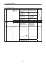
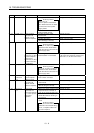
1. Pulse frequency of the command
pulse is too high.
Change the command pulse frequency to a
proper value.
2. Noise entered command pulses. Take action against noise.
AL.35 Command
pulse frequency
error
Input pulse
frequency of the
command pulse is
too high.
3. Command device failure Change the command device.
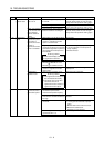
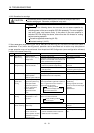
1. Servo amplifier fault caused the
parameter setting to be rewritten.
Change the servo amplifier.
2. Regenerative brake option not
used with servo amplifier was
selected in parameter No.0.
Set parameter No.0 correctly.
3. The number of write times to EEP-
ROM exceeded 100,000 due to
parameter write, etc.
Change the servo amplifier.
4.The alarm code output (parameter
No. 49) was set by the absolute
position detection system.
The absolute position detection system
and the alarm code output function are
exclusive. Set as either one of the two is
used.
AL.37 Parameter
error
Parameter setting is
wrong.
5.The alarm code output (parameter
No.49) was set with the
electromagnetic brake interlock
(MBR) assigned to pin CN1B-19.
The signal assignment function of the
electromagnetic interlock (MBR) to pin
CN1B-19 and the alarm code output
function are exclusive. Set as either one of
the two is used.