


15 - 5
15. ABSOLUTE POSITION DETECTION SYSTEM
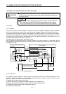
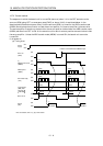
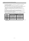
15.5 Signal explanation
When the absolute position data is transferred, the signals of connector CN1 change as described in this
section. They return to the previous status on completion of data transfer. The other signals are as
described in Section 3.3.2.
For the I/O interfaces (symbols in the I/O Category column in the table), refer to Section 3.6.
Signal name Code Pin No. Function/Application
I/O
category
Control
mode
ABS transfer
mode
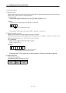
ABSM
(Note)
CN1B-8
While ABSM is on, the servo amplifier is in the ABS
transfer mode, and the functions of ZSP, TLC, and D01
are as indicated in this table.
DI-1
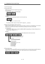
ABS request ABSR
(Note)
CN1B-9
Turn on ABSR to request the ABS data in the ABS
transfer mode.
DI-1
ABS bit 0 D01 CN1B-4
Indicates the lower bit of the ABS data (2 bits) which is
sent from the servo to the programmable controller in
the ABS transfer mode.
If there is a signal, D01 turns on.
DO-1
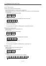
ABS bit 1 ZSP CN1B-19
Indicates the upper bit of the ABS data (2 bits) which is
sent from the servo to the programmable controller in
the ABS transfer mode.
If there is a signal, ZSP turns on.
DO-1
Send data ready TLC CN1B-6
Indicates that the data to be sent is being prepared in
the ABS transfer mode. At the completion of the ready
state, TLC turns on.
DO-1
Home position
setting
CR CN1A-8
When CR is turned on, the position control counter is
cleared and the home position data is stored into the
non-volatile memory (backup memory).
DI-1
P
(Position
control)
Note. When "Used in absolute position detection system" is selected in parameter No. 1, pin CN1B-8 acts as the ABS transfer mode
(ABSM) and pin CN1B-9 as the ABS request (ABSR). They do not return to the original signals if data transfer ends.