13 - 40
13. OPTIONS AND AUXILIARY EQUIPMENT
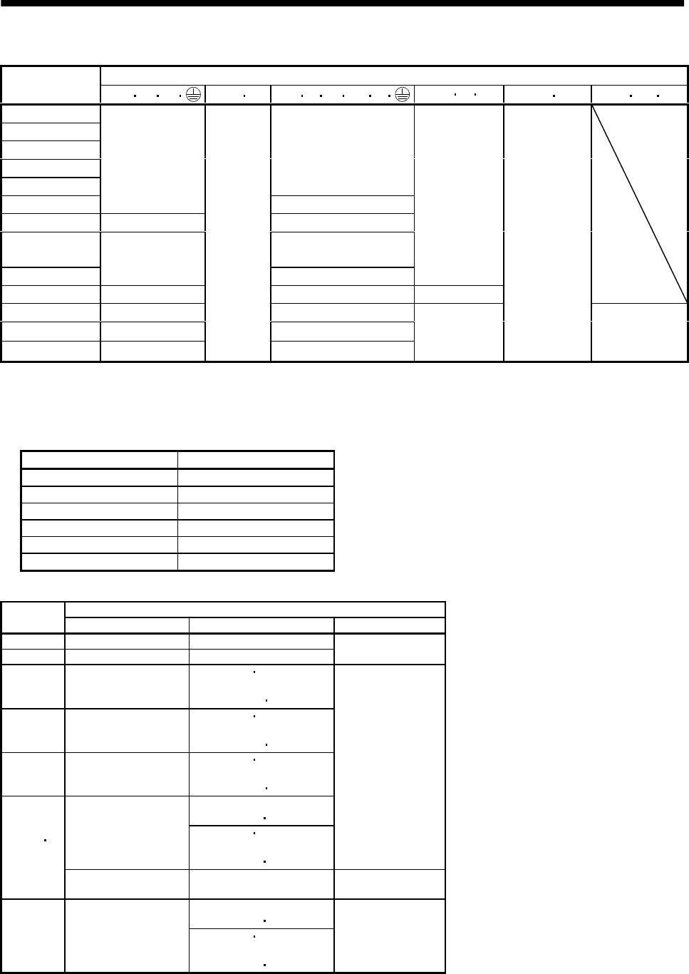
Table 13.1 Recommended wires
(Note 1) Wires [mm
2
]
Servo amplifier
1) L
1
L
2
L
3
2) L
11
L
21
3) U V W P
1
P
4)
P
C N5) B1B2 6) BU BV BW
MR-J2S-10A(1)
MR-J2S-20A(1)
MR-J2S-40A(1)
MR-J2S-60A
MR-J2S-70A
1.25 (AWG16) : a
MR-J2S-100A
2 (AWG14) : a
2 (AWG14) : a
MR-J2S-200A 3.5 (AWG12) : b 3.5 (AWG12) : b
MR-J2S-350A
(Note 2)
5.5 (AWG10) : b
MR-J2S-500A
5.5 (AWG10) : b
5.5 (AWG10) : b
2 (AWG14) : a
MR-J2S-700A 8 (AWG8) : c 8 (AWG8) : c 3.5(AWG12) : b
MR-J2S-11KA 14 (AWG6) :d 22 (AWG4) :e
MR-J2S-15KA 22 (AWG4) :e 30 (AWG2) :f
MR-J2S-22KA 50 (AWG1/0) :g
1.25
(AWG16)
60 (AWG2/0) :g
5.5(AWG10) : b
1.25 (AWG16)
2(AWG14)
Note 1. For the crimping terminals and applicable tools, refer to table 13.2:
2. 3.5mm
2
for use of the HC-RFS203 servo motor.
Use wires 6) of the following sizes with the brake unit (FR-BU) and power regeneration converter (FR-
RC).
Model Wires[mm
2
]
FR-BU-15K 3.5(AWG12)
FR-BU-30K 5.5(AWG10)
FR-BU-55K 14(AWG6)
FR-RC-15K 14(AWG6)
FR-RC-30K 14(AWG6)
FR-RC-55K 22(AWG4)
Table 13.2 Recommended crimping terminals
Servo amplifier side crimping terminals
Symbol
Crimping terminal Applicable tool Maker name
a 32959 47387
b 32968 59239
Tyco Electronics
cFVD8-5
Body YF-1
E-4
Head YNE-38
Dice DH-111
DH-121
d FVD14-6
Body YF-1
E-4
Head YNE-38
Dice DH-112
DH-122
e FVD22-6
Body YF-1
E-4
Head YNE-38
Dice DH-113
DH-123
Body YPT-60-21
Dice TD-124
TD-112
38-S6
Body YF-1
E-4
Head YET-60-1
Dice TD-124
TD-112
Japan Solderless
Terminal
(Note 1 2)
f
R38-6S
NOP60
NOM60
NICHIFU
Body YDT-60-21
Dice TD-125
TD-113
g (Note)R60-8
Body YF-1
E-4
Head YET-60-1
Dice TD-125
TD-113
Japan Solderless
Terminal
Note 1. Cover the crimped portion with an insulating tape.
2. Always use the recommended crimping terminals since they may not be installed depending on the size.


