1 - 22
1. FUNCTIONS AND CONFIGURATION
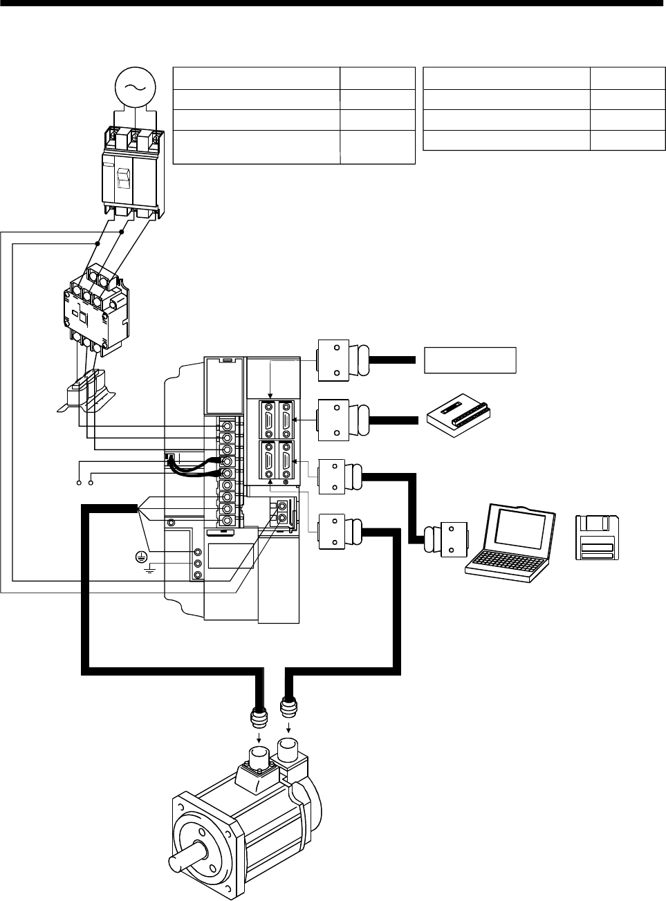
(3) MR-J2S-500A
To CN1A
Options and auxiliary equipment
No-fuse breaker
Magnetic contactor
MR Configurator
(Servo configuration software)
Regenerative brake option
Reference
Section 13.2.2
Section 13.2.2
Section 13.1.9
Section 13.1.1
Options and auxiliary equipment
Reference
Cables Section 13.2.1
Power factor improving reactor Section 13.2.3
3-phase 200V
to 230VAC
power supply
No-fuse
breaker
(NFB) or
fuse
Magnetic
contactor
(MC)
Power
factor
improving
reactor
(FA-BAL)
Servo amplifier
L
1
L
2
L
3
C
P
Regenerative brake
option
L
11
L
21
U
V
W
To CN1B
To CN3
To CN2
Personal
computer
MR Configurator
(Servo
configuration
software
MRZJW3-
SETUP151E)
Junction terminal
block
Command device
(Note)
Note. When using the regenerative brake option, remove the lead wires of the built-in regenerative brake resistor.


