


TASCAM DA-98HR 19
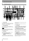
3 – Connections
This section explains how to connect other equip-
ment to the DA-98HR in a variety of situations. It is
not intended as a complete reference to the use of the
DA-98HR. See the appropriate sections for full
details of how these connectors are used.
NOTE
S
When making connections between the DA-98HR and
other equipment, whether audio or control, both the DA-
98HR and the other equipment must be turned
off
, other-
wise damage may be caused to the DA-98HR and/or the
other equipment.
Only use TASCAM-supplied and TASCAM-approved
cables when making connections to the DA-98HR. Though
the cables and connectors may resemble computer cables,
they serve different purposes, and meet a different set of
specifications. The use of cables other than TASCAM
cables will at best cause the equipment to work erratically,
and at worst cause damage to the equipment.
If the use of cables other than TASCAM cables causes or
results in damage, the warranty is voided.
3.1 Audio connection
Other audio equipment can be connected to the DA-
98HR either using optional analog or digital inter-
faces.
3.1.1 Analog audio connections
(optional IF-AN98HR)
All analog audio connections to the DA-98HR are
made through 25-pin D-sub connectors to the
optional analog slot 2-board set, IF-AN98HR.
This allows convenient and tidy cabling between the
DA-98HR and other units such as the TASCAM M-
1600 series of mixing consoles.
It is not recommended that you make up your own
cables—consult your TASCAM dealer for availabil-
ity of suitable ready-made cables. However, we rec-
ognize that every situation has its own unique
features, and there are occasions when a special cable
must be made.
Before starting to make the cable, we suggest you
contact your TASCAM dealer for full details of cable
specifications, etc.
The pinouts for both the
ANALOG OUTPUT and
INPUT connectors are given in the manual for these
boards, as are detailed specifications and
All audio inputs are balanced and are rated at a nom-
inal +4dBu level.
The impedance of the inputs is 20k
Ω and that of the
outputs is 10
Ω.
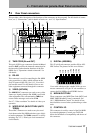
3.1.2 Digital audio connections (using
TDIF-1)
TDIF-1 digital audio input and output signals are car-
ried on the same 25-pin D-sub connector
u.
To carry signals between a DA-98HR and another
DTRS unit or a suitably-equipped digital mixing
console, use a PW-88D cable (1 meter long) or a PW-
88DL cable (5 meters long).
NOTE
Although the TDIF-1 and AES connectors use the same
type of 25-pin D-sub connector, it is not possible to connect
a TDIF-1 -equipped unit directly to an AES/EBU-equipped
unit. An interface such as the IF-AE8HR must be used to
convert the signals.
3.1.3 Digital audio connections (using
AES/EBU)
The AES/EBU connections (strictly speaking, this
format is AES3-1992 Amendment 3-1999) allow
direct connections between the DA-98HR and suit-
ably-equipped devices.
NOTE
If four dual-frequency (i.e. 88.2 kHz or 96 kHz) tracks have
been selected as the available tracks, see also 7.10.3,
“Setting the high-frequency AES/EBU I/O transfer mode”.
The AES x2 IO menu item (menu group A),
allows the choice of either
dual line or
high speed data connections. Note that this
menu option is only available when the dual-speed x
4 option is selected for the available tracks (see also
6.2.1, “Available tracks”).