


3 – Connections–Synchronization connections
20 TASCAM DA-98HR
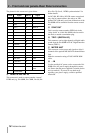
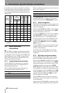
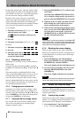
In all other cases, the data is transferred according to
the following table, where the numbers represent the
track which is being transferred. Italicized numerals
(e.g.
2
) indicate that the signal is being transferred at
double speed:
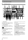
3.2 Synchronization
connections
The DA-98HR is equipped with sophisticated facili-
ties for control and synchronization with other units.
For full details of how to operate the DA-98HR with
other DTRS units, see 8, “DTRS synchronization”,
and for details of timecode synchronization, see 9,
“Operations related to timecode”.
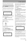
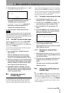
3.2.1 Analog timecode connections
The DA-98HR can be synchronized to externally-
generated timecode and is also equipped with an
internal timecode generator.
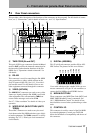
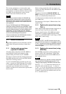
The two XLR timecode connectors
l carry bal-
anced signals with the following polarity:
However, unbalanced signals may be used, with only
pins 1 and 2 connected.
The
TIMECODE OUT connector transmits internally-
generated timecode or re-shaped or re-generated
timecode echoed from the
TIMECODE IN connector.
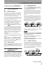
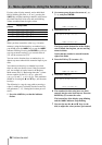
3.2.2 Video connections
These BNC connectors n are used to provide video
frame reference clocking when the DA-98HR is used
with video equipment.
The front panel
CLOCK switch j is used to change
between clock sources, and should be set to
VIDEO
when synchronizing to video sync.
Connect the
VIDEO IN connector of the DA-98HR to
the VIDEO OUT of a video sync generator unit.
This signal should be a 1 Vp-p composite signal.
If other equipment (such as other DTRS units) also
need the video frame reference clock, the signal
received at the
VIDEO IN is echoed at the VIDEO
THRU
connector.
If the DA-98HR is the last unit in the chain of video
equipment, there is no need to terminate it, as this
circuit is self-terminating.
For details of how the DA-98HR can be synchro-
nized to video frame information, see 9.7, “Video
resolution”.
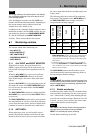
3.2.3 Word sync clock connections
This set of BNC connectors o is used to synchro-
nize the DA-98HR to other digital audio devices.
The front panel
CLOCK switch j is used to change
between clock sources, and should be set to
WORD
when synchronizing to an external word sync clock.
The
IN jack should be connected to the WORD
SYNC OUT of the digital audio device from which
the DA-98HR is to receive the synchronization clock.
Note the difference between the
OUT and the THRU
connectors.
OUT is used to carry word clock signals
generated by the DA-98HR, and
THRU is used to
echo the signals received at
IN.
If the DA-98HR is the last unit in the word clock
chain, there is no need to terminate it, as this circuit
is self-terminating.
Also note that if the DA-98HR is connected to other
DTRS units using a PW-88S cable as described in 8,
Output
channel
4x (2 tracks)
2x
(4 tracks)
2x (3 tracks) +
base (2 tracks)
2x (2 tracks) +
base (4 tracks)
base (8 tracks)
HS
a
a.High speed
DL
b
b.Dual line
1
111111
2
121112
3
——2223
4
——2224
5
233335
6
243346
7
——4457
8
——4568
Pin # Connection
1 Ground
2Hot
3Cold
IN (balanced) OUT (balanced)
Level 0.5 Vp-p to 10.0Vp-p 2Vp-p
Impedance
> 10k
Ω
< 100
Ω