


50 TASCAM DA-98HR
8 – DTRS synchronization
This section describes the techniques and methods to
be followed when the DA-98HR is linked to other
DTRS units (e.g. TASCAM DA-38, DA-88, DA-98,
DA-78HR, and of course other DA-98HR units).
In addition to control by a master DTRS unit, the a
chain of DA-98HR and other DTRS units can be con-
trolled by a remote control unit (for example, the RC-
898 remote control unit), or the control functions on
one of the TASCAM TM-D series of digital mixing
consoles. In these cases, the remote control device
should be connected to the REMOTE IN/SYNC IN
of the master unit. Machine IDs are unaffected by
this type of control.
Up to 16 DTRS units can be linked, for a total of 128
digital tracks.
If you are connecting DTRS units of different types
to the DA-98HR, use the DA-98HR as the master
unit and the other units as slave units.
8.1 Synchronization
connections
As described in 3, “Connections”, the cable to be
used when connecting the DA-98HR to other DTRS
units for synchronization purposes should be a PW-
88S cable. This is 1 meter (3 ft.) long.
NOTE
Be sure to use only the optional PW-88S sync cables. The
use of any other cables could damage the DA-98HR.
Be sure to connect the termination plug that comes with
the PW-88S cable to the last slave’s
SYNC OUT
connec-
tor , or else incorrect functions may occur.
Turn on all the DTRS units in your system, regardless of
whether you actually use all of them. A unit or units turned
off will make synchronization impossible.
To synchronize multiple DTRS units, use a pre-formatted
tape in the master unit, and also in the slave units. Since
the DTRS system uses ABS time to achieve synchroniza-
tion, tapes without ABS time recorded on them make syn-
chronization impossible.
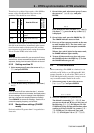
To synchronize multiple DTRS units, all the tapes in each
unit must be formatted using the same base sampling fre-
quency, or synchronization is impossible. It is, however,
possible to match dual- and quad-frequency tracks with
base-frequency tracks in a chain, provided that they all use
the same base frequency (44.1 kHz or 48 kHz).
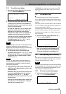
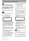
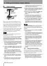
The synchronization connections form a “daisy-
chain”, with the master unit at the head of the chain,
and the last slave at the tail.
Connections are made from the
SYNC OUT t of
one unit to the
REMOTE IN/SYNC IN s of the next.
You do not need to change the
CLOCK setting from
INT or to connect the WORD SYNC connectors o on
any of the units if the system is a DTRS-only system.
NOTE
Always make and break all synchronization connections
with the power to all units in the chain turned OFF.
8.2 Machine ID and master/slave
settings
Each DTRS unit in the chain must be assigned a
unique machine ID. The unit at the head of the chain
(the master) should have ID number 1.
Though not strictly necessary, we suggest that IDs
are assigned in a consecutive sequential order from
the head of the chain.
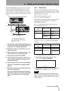
8.2.1 Differences between DTRS
models
The DA-98HR, DA-78HR, DA-98 and DA-38 all use
machine IDs that are set by software (the machine
must be turned on for the ID to be set). The values for
the IDs of these models start at “1” and go up to
“16”.
The switch on the back of the DA-88 is only opera-
tive when the unit is turned off. It is marked from “0”
through “F”.
When including DA-88s and other DTRS units in the
same chain, add 1 to the number shown on the DA-
88’s rear panel machine ID switch to make the DA-
88’s machine ID match the series of the DA-98HR
(and DA-38) IDs. Any DA-88 whose Machine ID is
not 1 (the switch has been set to a value other than 0)
will show its Slave ID briefly at power-on.