TELEDYNE INSTRUMENTS
460L Instruction Manual Getting Started
05228 Rev B 9
DCN 5164 PRINTED DOCUMENTS ARE UNCONTROLLED
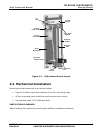
A
bsorption
Tube
Reference
Scrubber
UV Lamp
Power Supply
UV Lamp
Power Connector
UV
Lamp
Ozone Outlet
Manifold
Ozone Intlet
Manifold
UV
Detector
Measure / Reference
Valve
Sensor
Module PCA
UV Lamp
Housing
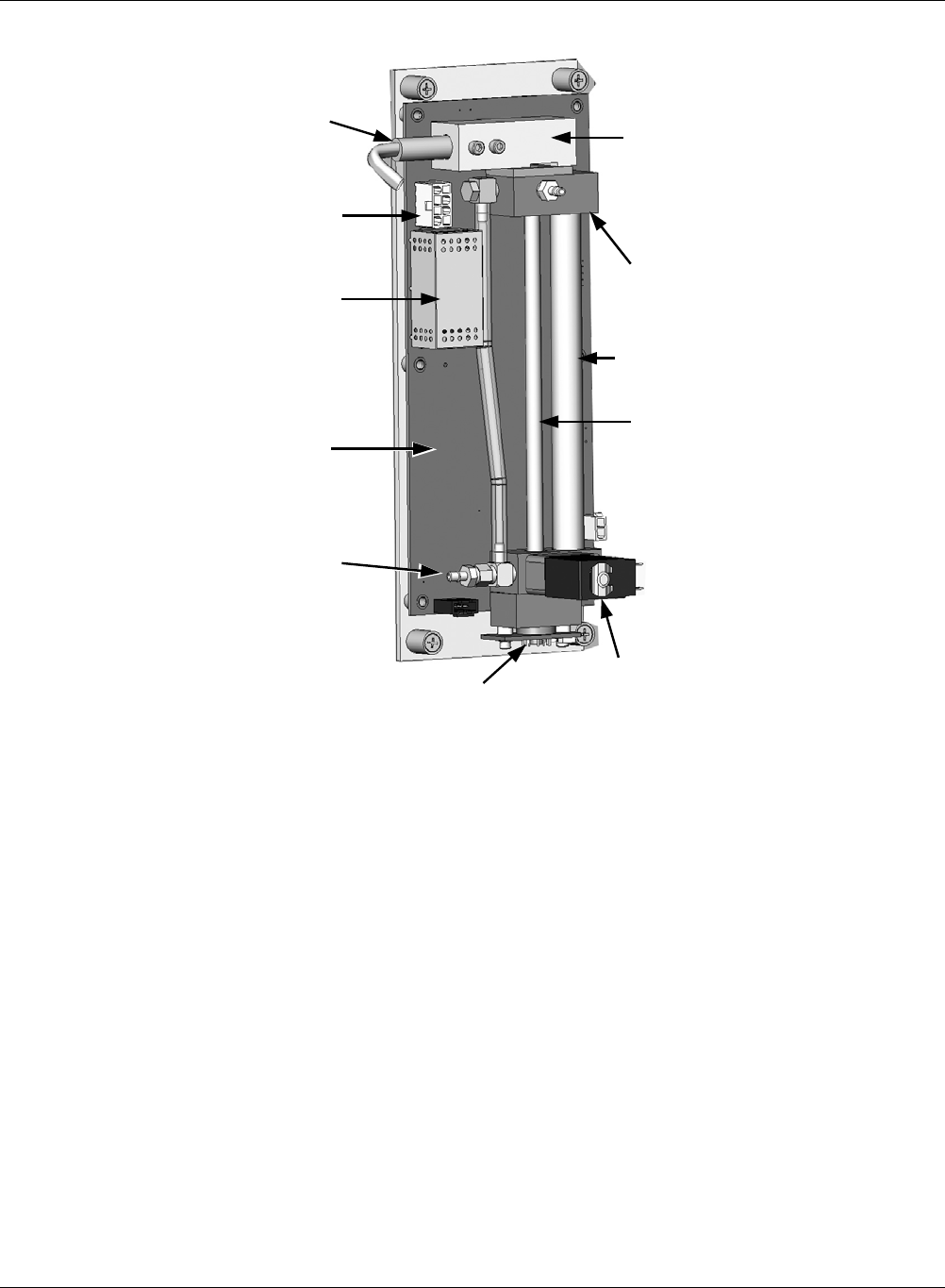
Figure 3-3 460L Sensor Module Layout
3.2. Mechanical Installation
Mount the enclosure securely to a vertical surface.
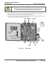
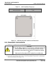
Figure 3-4 below shows the locations of the four mounting holes.
All four mounting holes should be used to secure the monitor.
Use stainless steel, 5/16” diameter bolts.
VENTILATION CLEARANCE:
When installing the monitor be sure to leave sufficient ventilation clearance.


