


TELEDYNE INSTRUMENTS
460L Instruction Manual Theory of Operation
05228 Rev B 59
DCN 5164 PRINTED DOCUMENTS ARE UNCONTROLLED
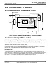
10.3.2. O
3
Sensor Module
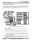
The heart of the 460 Monitor is the O
3
sensor module. This electromechanical assembly located at
the left hand side of the enclosure includes all of the pneumatic, mechanical and electronic
components needed to gather the data required to calculate the O
3
content of the source gas.
10.3.2.1. O
3
Sensor Components
UV Lamp: The ultraviolet light needed to detect O
3
is supplied by a mercury-vapor UV
lamp. This lamp is coated in a material that optically screens the UV radiation output to
remove the O
3
producing 185nm radiation. Only light at 254nm is emitted.
UV Lamp Heater : to operate efficiently the UV lamp must be kept at a temperature of
52˚C or higher. While the heat created by the lamp itself is usually sufficient to cause this,
under some ambient conditions additional heating is required. This additional heat is
provided by a DC heater, controlled by the sensor microprocessor.
Temperature Sensors: Two solid state temperature sensors are located in the O
3
sensor
module. They are:
Measurement Cell Temperature Sensor
: This sensor detects the temperature of the gas
inside the measurement cell. This information is used by the CPU as part of the O
3
concentration calculation (see Formula 10-3 in Section 10.1).
UV Lamp Temperature Sensor
: This sensor, attached to the UV lamp reports the
current temperature of the Lamp to the sensor microprocessor via the sensor module
A/D converter.
Both Sensors have built-in A/D converters and send digitized data directly to the monitors
CPU.
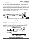
UV detector: A UV detector measures the two primary variables, I and I
0
(See Section
10.1.1) needed to compute the O
3
concentration of the source gas. They are:
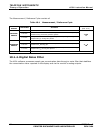
The first measurement (I) is taken during the measure period of the measure/
reference cycle (see Table 10-1) and records the intensity of the UV light passing
through the O
3
bearing source gas.
The second measurement (I
0
) occurs during the reference period of the cycle and
records the intensity of the light passing though gas from which the O
3
has been
removed.
This detector is a specially designed vacuum diode that only reacts to radiation at or very
near a wavelength of 254nm and outputs a voltage that varies in direct relationship with
the light’s intensity. The wavelength specificity of the detector is high enough that no extra
optical filtering of the UV light is needed.
Two stages of the preamplifier are used to amplify the output signals of the detector to a
level readable by the A/D Converter circuitry of the monitor’s sensor module. The first
stage of amplification is located on the PCA’s on which the detector itself is mounted. The
second stage of amplification is located on the sensor module PCA.