


TELEDYNE INSTRUMENTS
Theory of Operation 460L Instruction Manual
58 05228 Rev B
PRINTED DOCUMENTS ARE UNCONTROLLED DCN 5164
10.3. Electronic Theory of Operation
Sensor Module
Main Board
Status
Output
Drivers
Sensor OK
Relay
HI Alarm Relay
HI-HI Alarm
Relay
Analog and Digital I/O Connector
Status
Output
Serial I/O
Analog
Outputs
Control
Inputs
CPU Board
Optional 4-20 mA
outpt
Analog
Ouput
RS-232 / RS-485
Port
CPU
Front Panel
LED Display
Display
Driver
Board
Keyboard
Status LED’s
Sensor OK
Invalid Reading
Lamp Low
Alarm Active
I
2
C Bus
Micro-processor
UV Lamp
Heater
Lamp
Temperature
Sensor
Measurement
Cell
Temperature
Sensor
I
2
C Bus
M/R Valve
M/R Valve
Relay
Amplifier
Detector Assy
Measurement
Detector
Pre
Amp
Sample Gas
Pressure
Sensor
RS-485
M/R Valve
Control
Circuitry
Control
Outputs
UV Lamp
Power
Supply
UV Lamp
High
Resolution
A/D
Low
Resolution
A/D
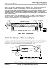
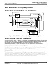
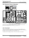
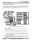
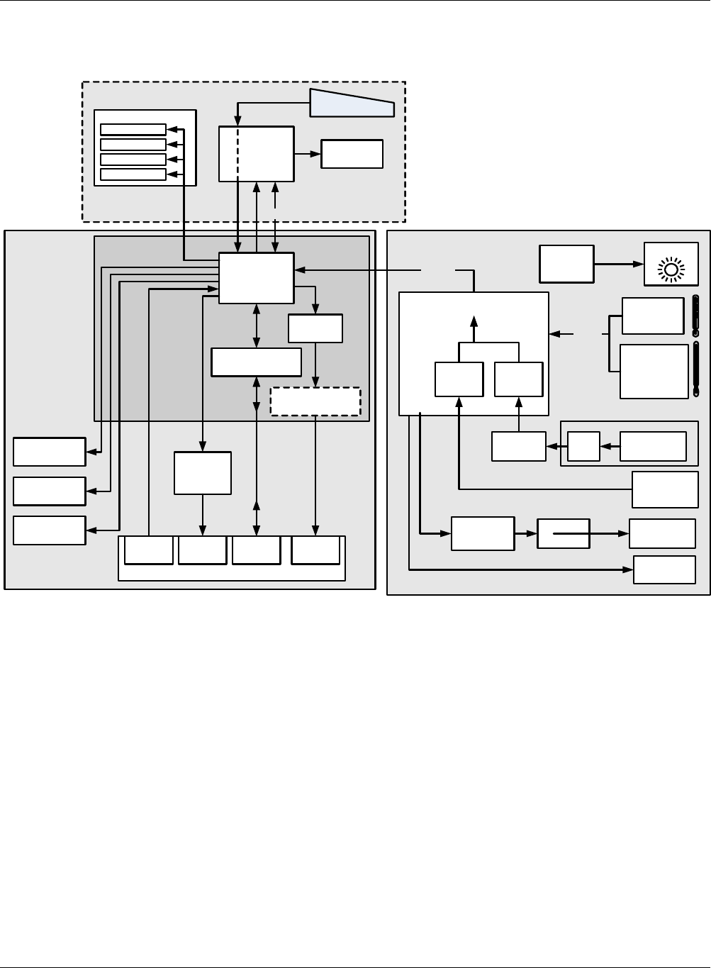
Figure 10-5 460L Electronic Block Diagram
Electronically, the 460L is of modular design (see Figure 10-5). Each Sub-module performs a
specific set of functions as described in Sections 10.3.1 through 10.3.5.
10.3.1. Main Board
This printed circuit assembly provides interconnection between the monitor’s other electronic
modules; some opto-isolated signal buffers for the digital status outputs and control inputs and is
the location of the three solid state output relays (see Section 3.5.5).
The monitor’s main power supply (see Section 10.3.5) is also located on this assembly.