


TELEDYNE INSTRUMENTS
Getting Started 460L Instruction Manual
16 05228 Rev B
PRINTED DOCUMENTS ARE UNCONTROLLED DCN 5164
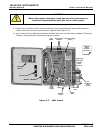
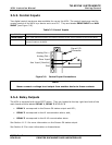
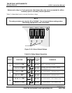
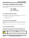
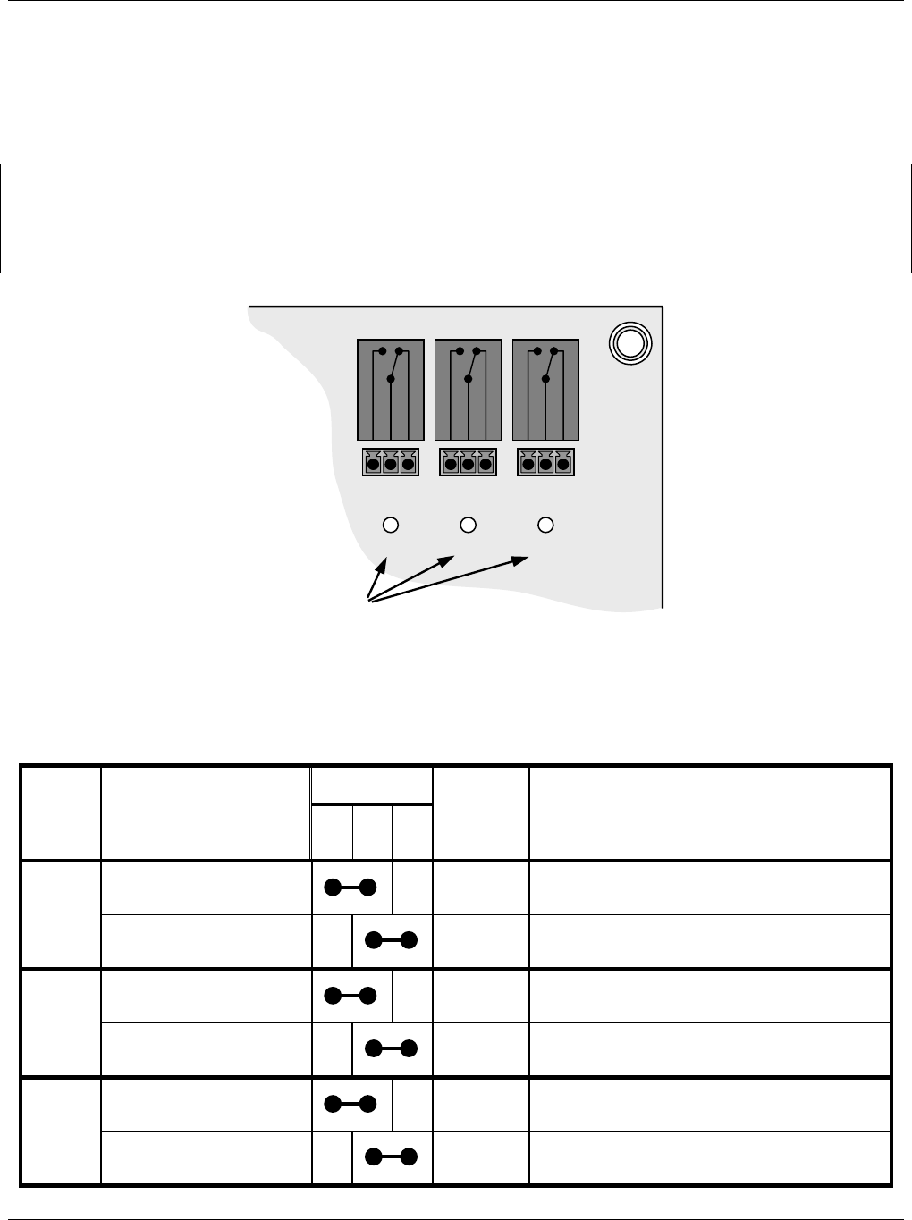
Below each relay is a 3-pin connector that allows the relay to be connected for either
normally open or normally closed operation.
Table 3-4 describes how to connect the alarm relays.
NOTE
The relay contacts are rated to 3A at 240VAC. Do not exceed these ratings when
connecting equipment to the instrument.
RELAY 1
N.O.
COM
N.C.
D6
RELAY 2
N.O.
COM
N.C.
D7
RELAY 3
N.O.
COM
N.C.
D8
STATUS LEDS
Figure 3-10 Alarm Output Relays
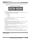
Table 3-4 Relay Output Operation
RELAY PIN
STATE
2
RELAY FUNCTION
N.
O.
C
O
M
N.
C.
STATUS
LED
1
COMMENTS
SENSOR OK ON
D6 ON 460L is operating normally
1
SENSOR OK OFF
D6 OFF
Problem with the O
3
sensor module.
See Section 11.2.
HI Alarm ON
D7 ON O
3
concentration > HI alarm limit
2
HI Alarm OFF
D7 OFF O
3
concentration < HI alarm limit
HI-HI Alarm ON
D8 ON O
3
concentration > HI-HI alarm limit
3
HI-HI Alarm OFF
D8 OFF O
3
concentration < HI-HI alarm limit