


TELEDYNE INSTRUMENTS
460L Instruction Manual Theory of Operation
05228 Rev B 61
DCN 5164 PRINTED DOCUMENTS ARE UNCONTROLLED
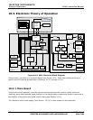
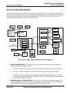
10.3.3. CPU Board
In addition to being responsible for all I/O functions and managing the state of the monitors
various status indicators and alarms (see below), the 460L’s CPU also calculates the monitor’s
offset during zero point calibration (see Section 8.1) and converts O
3
concentration data from ppb
units into ppm units if necessary.
10.3.3.1. I/O Functions
Display Data: Two-way communications between the CPU and the Display driver module
is handled via an
I
2
C interface. I
2
C is a two-wire, clocked, bi-directional, digital serial I/O
bus that is used widely in commercial and consumer electronic systems.
Keyboard Input: The three keys/buttons on the front panel (two zero keys and the
Alarm Resert key) are sensed directly by the CPU as simple digital contact closures.
Analog Output: The 460L is equipped with one analog output which reports the current
O
3
concentration currently being measured by the monitor. During auto zero operation the
last valid concentration value is held until the auto zero procedure is completed. This
output is factory configurable as either a 0-5 VDC signal or a 4-20 mA signal.
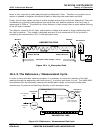
Serial I/O: A standard RS-232 or RS-485 serial communications port. Section 3.5.4
describes how to configure and make connections to this port. Chapter 7 describes the
syntax and commands available for use.
Control Inputs: These inputs are used to initiate certain operations. (see Table 3-3).
They are triggered by providing a contact closure or low impedance current path between
the input and the ground pin (GND – see Figure 3-9). This can be done by using a
mechanical switch or isolated transistor output from another device, such as a PLC.
10.3.3.2. Status and Alarm Functions
Relay Outputs: The 460L is equipped with three relay three SPDT relay. They are located
at the top right hand side of the main board and are labeled RELAY 1, RELAY 2 & RELAY 3.
RELAY 1 corresponds to the Sensor OK status output and LED;
RELAY 2 corresponds to the HI concentration alarm, and;
RELAY 3 corresponds to the HI-HI concentration alarm
Status LED’s: Based on data received from the sensor module, it activates and
deactivates the four status LED’s located on the monitor’s front panel (see Section 11.2.4).
Status Outputs: Logic-Level voltages are output via optically isolated NPN transistors,
which sink up to 50 mA of DC current. They are accessed through connector J2 on the
main board. Several of these outputs convey good/bad information about key monitor
operational conditions (see Section 11.2). Others reflect the status of the monitors O
3
concentration alarms.
These outputs can be used to interface with devices that accept logic-level digital inputs,
such as programmable logic controllers (PLC’s). Each Status bit is an open collector output
that can withstand up to 40 VDC. All of the emitters of these transistors are tied together