


TELEDYNE INSTRUMENTS
460L Instruction Manual Theory of Operation
05228 Rev B 55
DCN 5164 PRINTED DOCUMENTS ARE UNCONTROLLED
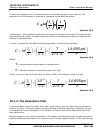
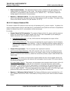
10.2. Pneumatic Theory of Operation
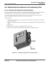
10.2.1. Basic Pneumatic Flow And Flow Control
O
3
Measurement Cell
Particulate Filter
Flow Meter
MEASURE
REFERENCE
VALVE
O
3
IN
Exhaust
Out
Monitor Enclosure
PUMP
Flow Meter Valve
1
3
2
O
3
Scrubber
O
3
DESTRUCT
(Optional)
Gas
Pressure Sensor
ABSORPTION TUBE
Measure Cycle Gas Path
Reference Cycle Gas Path
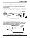
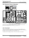
Figure 10-3 460L Internal Pneumatic Diagram – Basic Configuration
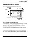
10.2.2. Internal Pump and Flow Control
Air flow through the M460L O
3
Monitor is supplied by a single-diaphragm, brushless DC pump that
pulls air though the monitor. Since diaphragm pumps necessarily heat and compress the air they
are pumping and since both temperature and pressure fluctuations can effect the O
3
measurement, the pump is placed down stream from the measurement cell to avoid any
inadvertent effects resulting from the pumping action.
An adjustable needle-restrictor valve and flow gauge, located on the front panel of the monitor
allow the user to manually adjust the gas flow rate through the monitor.
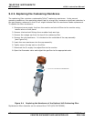
Particulate Filter
To remove particles in the sample gas which might clog airways or foul the measurement cell
optics, the monitor is equipped with a glass-fiber membrane filter of 25 mm diameter with a pore
size of 1.5 microns. The filter is located inside the black housing on the bottom of the monitor.
See Section 9.1 for location and instruction for replacing the filter element.