TELEDYNE INSTRUMENTS
Getting Started 460L Instruction Manual
10 05228 Rev B
PRINTED DOCUMENTS ARE UNCONTROLLED DCN 5164
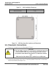
Table 3-1 460L Ventilation Clearances
AREA MINIMUM REQUIRED CLEARANCE
Sides of the monitor 1 inch
Above and below the monitor. 1 inch
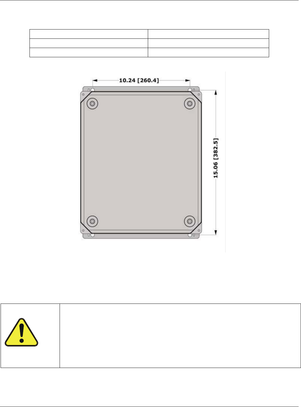
Figure 3-4 460L Mounting Hole Locations and Dimensions
3.3. Pneumatic Connections
1. Connect a ¼” exhaust line to the fitting labeled ‘Exhaust.’
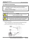
CAUTION
If using the 460L to measure O
3
levels that are ≥100 ppb exhaust gas
from the MODEL 460L may contain dangerous levels of ozone!
The optional ozone destruct (see Section 5.3) should be installed
and
Make sure that the exhaust line is vented to an outside area.
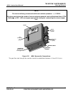
2. Connect the ozone delivery line to the ¼” inlet fitting labeled “Ozone Inlet” on the bottom
face of the enclosure (See Figure 3-5.)


