TELEDYNE INSTRUMENTS
460L Instruction Manual Table of Contents
05228 Rev B v
DCN 5164 PRINTED DOCUMENTS ARE UNCONTROLLED
List of Figures
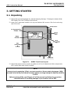
Figure 3-1 M460L Front Cover Layout .............................................................................7
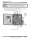
Figure 3-2 460L Layout ................................................................................................8
Figure 3-3 460L Sensor Module Layout ...........................................................................9
Figure 3-4 460L Mounting Hole Locations and Dimensions ............................................... 10
Figure 3-5 460L Pneumatic Connections........................................................................ 11
Figure 3-6 Location of Electrical Connectors................................................................... 12
Figure 3-7 Signal I/O Connector Pin Assignments ........................................................... 13
Figure 3-8 Digital Status Output Connections................................................................. 14
Figure 3-9 Control Input Connections ........................................................................... 15
Figure 3-10 Alarm Output Relays................................................................................... 16
Figure 3-11 RS-232/RS-485 Jumper Location and Settings................................................ 18
Figure 3-12 Typical RS-232 and RS-485 Connections........................................................ 19
Figure 8-1 Setup for Measuring Current Output Signal Level ............................................ 43
Figure 8-2 Location Current Output Adjustment Potentiometers ....................................... 44
Figure 9-1 Changing the Particulate Filter...................................................................... 45
Figure 9-2 Changing the Particulate Filter...................................................................... 46
Figure 9-3 Draining the Optional H
2
O Coalescing filter..................................................... 47
Figure 9-4 Replacing the Membrane of the Optional H
2
O Coalescing filter........................... 48
Figure 9-5 UV Lamp Set Screws and Calibration Test Points............................................. 49
Figure 10-1 O
3
Absorption Path ..................................................................................... 53
Figure 10-2 Reference / Measurement Gas Cycle ............................................................. 53
Figure 10-3 460L Internal Pneumatic Diagram – Basic Configuration................................... 55
Figure 10-4 460L Internal Pneumatic Diagram with Optional Sample Conditioning ................ 56
Figure 10-5 460L Electronic Block Diagram ..................................................................... 58
Figure 10-6 460L Power Distribution Block Diagram ......................................................... 63
Figure 12-1 Triboelectric Charging ................................................................................. 69
Figure 12-2 Basic anti-ESD Workbench........................................................................... 72
LIST OF TABLES
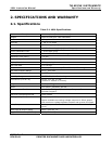
Table 2-1 460L Specifications.......................................................................................5
Table 3-1 460L Ventilation Clearances ......................................................................... 10
Table 3-2 Digital Status Output Descriptions................................................................. 14
Table 3-3 Control Inputs............................................................................................ 15
Table 3-4 Relay Output Operation............................................................................... 16
Table 3-5 Serial I/O Port Connection ........................................................................... 17
Table 3-6 Serial Port Configuration.............................................................................. 20
Table 6-1 Status LED’s .............................................................................................. 25
Table 6-2 Concentration Alarm Default Settings ............................................................ 26
Table 7-1 Serial Port Command Summary.................................................................... 28
Table 7-2 VAR_INDEX List for VGET Command ............................................................. 37
Table 7-3 VAR_INDEX List for VSET Command.............................................................. 39
Table 10-1 Measurement / Reference Cycle.................................................................... 54
Table 11-1 Digital Status Outputs Definitions ................................................................. 65
Table 11-2 Status LED / Output Trouble shooting Truth Table........................................... 67
Table 11-3 Alarm Output Troubleshooting...................................................................... 67
Table 12-1 Static Generation Voltages for Typical Activities .............................................. 70
Table 12-2 Sensitivity of Electronic Devices to Damage by ESD......................................... 70


