


TELEDYNE INSTRUMENTS
460L Instruction Manual Theory of Operation
05228 Rev B 63
DCN 5164 PRINTED DOCUMENTS ARE UNCONTROLLED
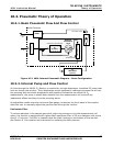
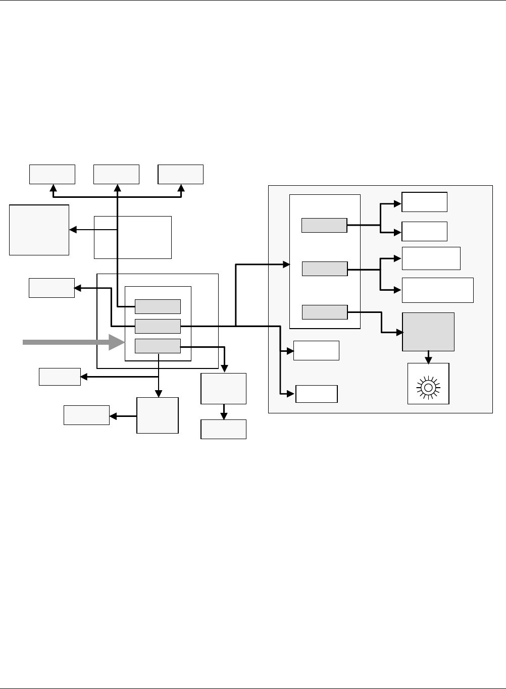
10.3.5. Power Distribution
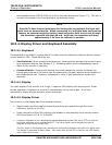
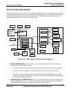
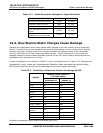
The 460L operates on 90 to 260 VAC power at either 50Hz or 60Hz. As illustrated in Figure 10-6
below, power enters the monitor via a standard 3-conductor power cord through a hole provided
in the bottom of the casing. In order to maintain the IP (NEMA4X) rating of the enclosure, an
appropriate sealed conduit connector should be used.
O
3
Sensor Module
Main Power Supply
M / R Valve
CPU
Board
Measurement
Detector
MEASUREMENT CELL
TEMPERATURE
SENSOR
UV Lamp
Heater
UV LAMP
Serial I/O
Port
Analog
Outputs
Status I/O
Status LEDS
Sensor OK
Invalid Reading
Lamp Low
Cell Dirty
Display
Driver
Board
Keyboard
LED Display
Sensor Assembly
Power Supply
Main Power Supply
UV Lamp
Power Supply
200VAC 3kHz
(1000VAC Peak)
Pressure
Sensor
UV LAMP
TEMPERATURE
SENSOR
+ 12 VDC
+ 15 VDC
V
acuum
Pump
+ 5 VDC
VAC IN
Output
Relays
Output
Relays
Drivers
± 9 VDC
+ 12 VDC
+5 VDC
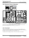
Figure 10-6 460L Power Distribution Block Diagram
MAIN POWER SUPPLY: AC line power is converted and stepped down to several DC
voltages by the main power supply:
+12 VDC: Powers the vacuum pump, the display driver and the alarm relay outputs.
+5 VDC: The basic voltage on which the CPU and logic level circuitry operates.
+15 VDC: Source voltage for the keyboard (where it is regulated down to +5 VDC),
the UV lamp heater; the measure / reference valve a secondary power supply located
on the sensor module assembly.
SENSOR MODULE POWER SUPPLY: Using +15 VDC from the main power supply, this
circuitry generates the +5, +12 & ±9 VDC supplies needed to operate its own on-board
logic devices and the various components of the O
3
sensor module.