


TELEDYNE INSTRUMENTS
460L Instruction Manual Calibration
05228 Rev B 43
DCN 5164 PRINTED DOCUMENTS ARE UNCONTROLLED
8. Enter the New Slope into the M460M’s memory enter it in. Type:
<address>VSET:<VAR Number>,<New Slope Value><CR>
EXAMPLE
3VSET:16,1.048<CR>
Where:
The address of the M460M is 3
The O3 SLOPE VAR is number 16
The New Slope is = 1.013
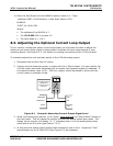
8.3. Adjusting the Optional Current Loop Output
If your monitor includes the option current loop output you may need to check or adjust the
actual current levels of the output to ensure that it matches the input requirements of your
recording device. See Section 3.5.1 for details on making connections to the 4-20mA output.
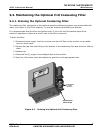
To manually adjust the zero and span points of the 4-20mA analog output:
1. Disconnect the monitor from AC power.
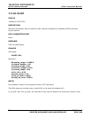
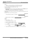
2. Connect current measuring meter in series with the 4-20mA output. For best results, the
4-20mA output should be calibrated with the actual load (measuring device) attached. If
this cannot be done, then a 250 – 500 ohm resistor should be placed in series with the
current meter to simulate a load.
mA
IN OUT
ANALOG OUT
ANALOG OUT -
I IN +
I IN -
Recording
Device
Monitor
See Figure 3-6 for
pin assignments o
f
the signal I/O
connector on the
rear panel.
Figure 8-1 Setup for Measuring Current Output Signal Level
3. While reconnecting the monitor to AC power, press and hold
the “Alarm Reset” button on
the front panel. This will cause the monitor to enter the analog output step mode. The
display on the monitor will display “A 0” indicating that it is in the analog output step
mode and at the 0% point (see Section 7.3.4).
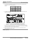
4. At
this point th
e analog output should read somewhere near 4.0mA. Adjust the “Zero”
potentiometer on the 4-20mA PCA (See Figure 8-2) as necessary.