


TELEDYNE INSTRUMENTS
Getting Started 460L Instruction Manual
14 05228 Rev B
PRINTED DOCUMENTS ARE UNCONTROLLED DCN 5164
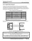
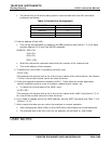
3.5.2. Digital Status Outputs
The 460L has six assigned digital status outputs for indicating error and operational status
conditions of the monitor as well as the status of its O
3
concentration alarms (see Table 3-2).
These outputs are in the form of opto-isolated open-collector transistors. They can be used to
drive status LED’s on a display panel or interface to a digital device such as a Programmable Logic
Controller (PLC). Several of the status outputs are useful tools for diagnosing sensor and system
level malfunctions (see Section 11.2 for more information).
Table 3-2 Digital Status Output Descriptions
LABEL
1
NAME OPERATION
STATUS OUT 1
2
Sensor O.K. Normally On
STATUS OUT 2
2
Invalid Reading Normally Off
STATUS OUT 3
2
Lamp Low Normally Off
STATUS OUT 4 Alarm Active Normally Off
STATUS OUT 5 HI Alarm Status Normally Off
STATUS OUT 6 HI-HI Alarm Status Normally Off
STATUS COM Common Pin for all Status Outputs N/A
1
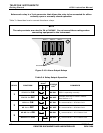
See Figure 3-7 for pin locations of the these output lines on the monitor’s 16-pin I/O
connector
2
See Section 11-2 for definitions and interpretations of these output.
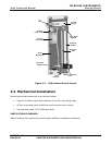
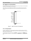
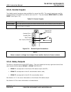
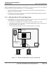
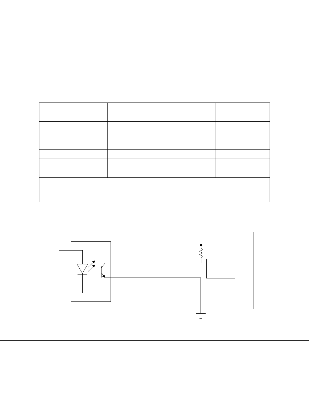
Figure 3-8 shows the most common way of connecting the digital outputs to an external device
such as PLC.
Opto-Isolator
Ground
Connection
Provided by PLC
+5V
460M
PLC OR OTHER DEVICE
Digital Input
STATUS COM (Emitter)
Status Outputs 1-6 (Collector)
Figure 3-8 Digital Status Output Connections
Note
Most devices, such as PLC’s, have internal provision for limiting the current that the
input will draw from an external device.
When connecting to a unit that does not have this feature, external dropping-resistors
must be used to limit the current through the transistor output to 50mA or less.
At 50 mA, the transistor will drop approximately 0.2V from its collector to emitter.