


TELEDYNE INSTRUMENTS
Calibration 460L Instruction Manual
44 05228 Rev B
PRINTED DOCUMENTS ARE UNCONTROLLED DCN 5164
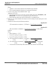
5. The monitor will automatically generate the nominal signal level by producing a 25%
increment output level on the current loop.
EXAMPLE
OUTPUT LEVEL NOMINAL SIGNAL
LEVEL
0% 4mA
25% 8mA
50% 12mA
75% 16mA
100% 20mA
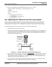
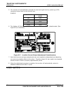
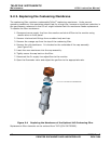
6. The display will then show “A100” (four times). Adjust the “Span” potentiometer (See
Figure 8.2) as necessary.
Span
Pot.
Zero
Pot.
Figure 8-2 Location Current Output Adjustment Potentiometers
7. Note that the zero and span adjustments are not completely independent and adjusting
one point may slightly affect on the other. Therefore steps 4-6 may need to be repeated
several times in order to properly adjusted both points.
8. When the adjustment process is complete, the monitor will automatically restart in
standard measurement after 5 cycles.
USER NOTES: