TELEDYNE INSTRUMENTS
460L Instruction Manual Getting Started
05228 Rev B 13
DCN 5164 PRINTED DOCUMENTS ARE UNCONTROLLED
3.5. Signal I/O Connections
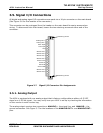
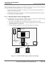
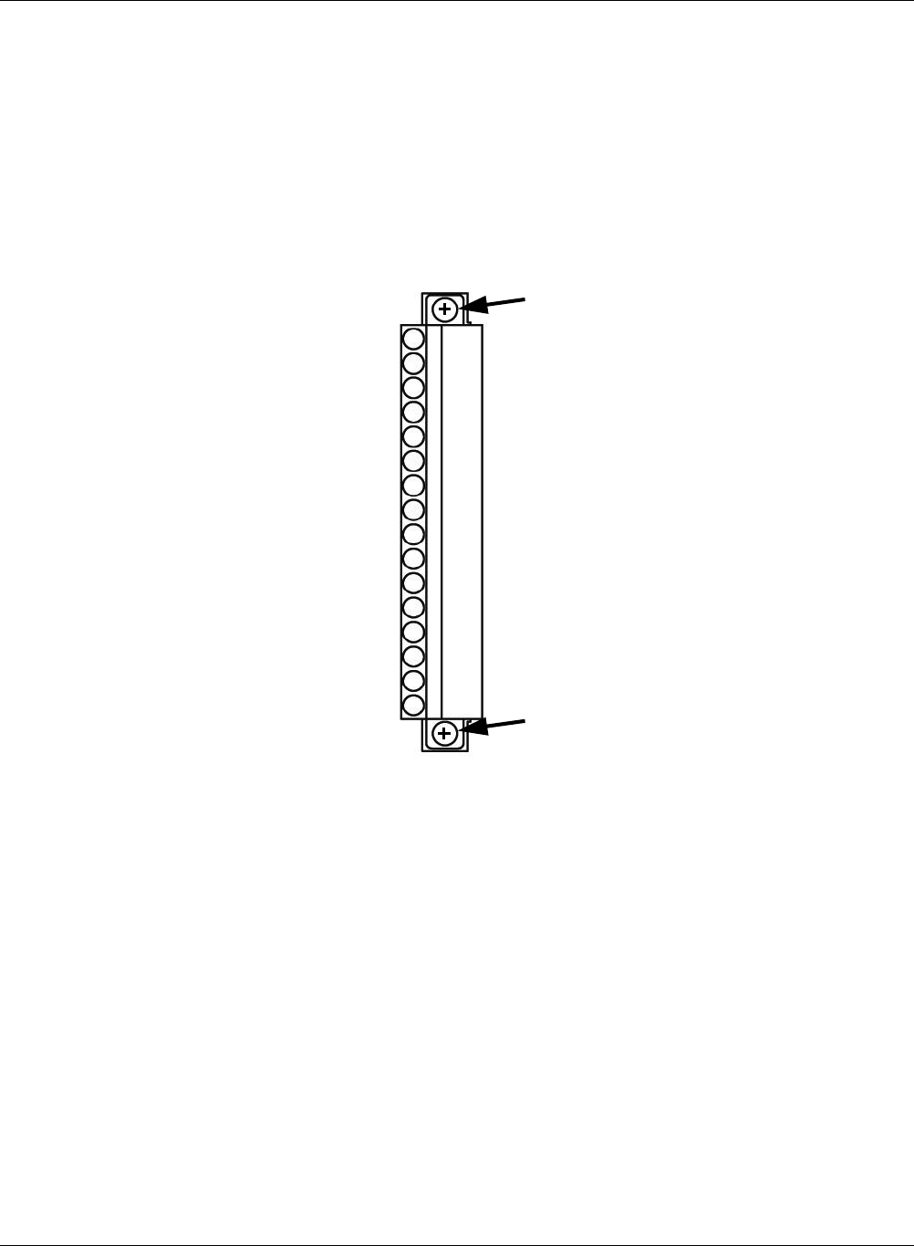
All digital and analog signal I/O connections are made via a 16-pin connector on the main board
(See Figure 3-6 for the location of the connector.)
This connector can be unplugged from the header on the main board for easier access when
wiring. To disconnect from main board, loosen the two retaining screws at either end of the
connector.
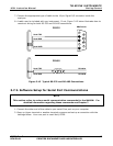
Analog Out +
Analog Out -
Zero Input
Aux Input
Gnd
Status Out 1
Status Out 2
Status Out 3
Status Out 4
Status Com
Serial TX
Serial RX
Serial GND
Status Out 5
Status Out 6
Retaining Screw
Retaining Screw
Figure 3-7 Signal I/O Connector Pin Assignments
3.5.1. Analog Output
The 460L is equipped with one analog output that is factory configurable as either a 0-5 VDC
signal or a 4-20 mA signal. You may verify how your 460L is set up by checking the information
on the
monitor’s serial number tag.
The analog output requires two connections: ANALOG +, the signal line, and ANALOG–, the
ground connection. See Figure 3-7 for the locations of the ANALOG OUT + and ANALOG OUT–
pins.


