


TELEDYNE INSTRUMENTS
Theory of Operation 460L Instruction Manual
62 05228 Rev B
PRINTED DOCUMENTS ARE UNCONTROLLED DCN 5164
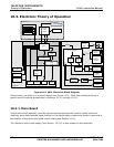
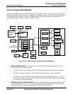
and available at the STATUS COM pin of J2 on the main board (see Figure 3-7). This pin is
normally connected to the input ground of the external device.
NOTE
Most PLC’s have internal provisions for limiting the current that the input will
draw from an external device. When connecting to a unit that does not have this
feature, an external dropping resistor must be used to limit the current through
the transistor output to less than 50 mA. At 50 mA, the transistor will drop
approximately 1.2V from its collector to emitter.
10.3.4. Display Driver and Keyboard Assembly
10.3.4.1. Keyboard
The keyboard of the M460L is comprised of 3 contact closure button/keys that are directly sensed
by the monitor’s CPU. These Switches are:
Zero Switches: When pressed simultaneously, these switches activate the monitor’s auto
zero calibration feature (see Section 8.1). Activating either switch independently has no
affect on the monitor’s’ operation.
Pressure Switch: Pressing and holding this switch causes the monitor to display the
current gas pressure of the source gas as measured by the gas pressure sensor located on
the measurement cell. Pressure is displayed in units of psia (pounds per square inch
absolute).
10.3.4.2. Display
The main display of the monitor is a 4-digit, 7-segment LED display with decimal point. Under
normal operation it displays the current O
3
concentration of the source gas. It can also
momentarily display the gas pressure of the source gas.
10.3.4.3. Display Driver
The circuitry on the display has driver several functions.
Signal levels from the three front panel key/buttons are passed through the driver
unaltered, directly to the CPU.
Under command of the CPU a control chip located on this assembly turns the four status
LED’s(see Section 112 & 11.3) ON/OFF
A
bipolar integrated circuit decodes the serial data sent by the CPU via an I
2
C bus and the
individual segments of the display ON/OFF. The clock signal used to decode this data is
supplied by the monitor’s main CPU.
The four digits on the display are controlled by multiplexing between two pairs of 2 digits each.
The display is operated in static mode. Each value sent by the CPU is held on the LED display
until a new value is sent.