


4
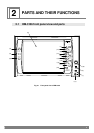
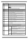
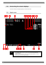
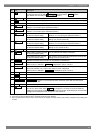
Table 2.1 Front panel parts
No. Part Description of function
(1) POWER switch/LED
Used to turn the power ON and OFF. (*1) (The LED lights up green while the power is
supplied.)
(2) REMOTE switch/LED
Used to lock the panel switches and enable the monitor to be operated by remote
control. (*3)
The monitor’s settings are saved at the same time as the panel switches are locked.
Wait appears at the bottom right of the screen while the settings are being saved.
(*2)
The saved settings are loaded when the power is turned on.
(The LED lights up yellow while remote control is enabled.)
(3) LCD display This is where the images are displayed.
(4) SDI A switch Used to display the images which are input to SDI input channel A on the screen.
(5) SDI B switch Used to display the images which are input to SDI input channel B on the screen.
(6) ANALOG switch
Used to display the images which are input to the ANALOG connector on the screen.
Each time the ANALOG switch is pressed, the images are switched between
COMPOSITE and COMPONENT.
(7) F1/- switch
Used to execute the function allocated to the switch at any time except during menu
operations. (Refer to “3.4.42 Allocating functions to the front panel switches.”)
During menu operations, the switch is used to move the cursor to the left or upward or
reduce the value which is being adjusted.
(8) F2/+ switch
Used to execute the function allocated to the switch at any time except during menu
operations. (Refer to “3.4.42 Allocating functions to the front panel switches.”)
During menu operations, the switch is used to move the cursor to the right or downward
or increase the value which is being adjusted.
(9) F3/ENT switch
Used to execute the function allocated to the switch at any time except during menu
operations. (Refer to “3.4.42 Allocating functions to the front panel switches.”)
During menu operations, the switch is used to enter the value which is being adjusted
and move between hierarchical levels.
(10) F4/ESC switch
Used to execute the function allocated to the switch at any time except during menu
operations. (Refer to “3.4.42 Allocating functions to the front panel switches.”)
During menu operations, the switch is used to cancel the value of the setting which is
being changed and to exit the adjustment.
(11) MENU switch
Used to turn the menu screen ON or OFF.
When the menu screen is ON: Switches (7) to (10) function as the -, +, ENT and ESC
switches, respectively.
When the menu screen is OFF: Switches (7) to (10) function as the F1, F2, F3 and F4
switches, respectively.
(12) BRIGHT switch
Used to adjust the brightness.
(Refer to “3.4.13 Adjusting the offset level of the brightness signals.”)
(13) CONTRAST switch
Used to adjust the contrast.
(Refer to “3.4.14 Adjusting the contrast of the brightness signals.”)
At the YPbPr
(ColorSpace)
setting
Used to adjust the chroma.
Each time the switch is pressed, its setting changes in the following
sequence: chroma → Pb → Pr → exit adjustment. (Refer to “3.4.15
Adjusting the Pb (Cb) value” to “3.4.17 Adjusting the Pb (Cb) and Pr (Cr)
values simultaneously (adjusting the chroma).”)
(14) CHROMA switch
At the GBR
(ColorSpace)
setting
The chroma cannot be adjusted.
At the YPbPr
(ColorSpace)
setting
Used to adjust the peak value or hue.
The peak value can be adjusted when peaking is at ON. Each time the
switch is pressed, its setting changes in the following sequence: peak →
hue → exit adjustment. (Refer to “3.4.19 Adjusting the peaking value” to
“3.4.21 Adjusting the hue.”)
(15) PEAK/HUE switch
At the GBR
(ColorSpace)
setting
Used to adjust the peak value.
The peak value can be adjusted when peaking is at ON. The hue cannot
be adjusted. (Refer to “3.4.19 Adjusting the peaking value.”)