


9
3
3
OPERATION
3.1 Connection procedure
This section describes how to connect the DM-3106.
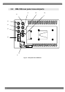
(1) Connecting the power supply
Check that the monitor’s POWER switch is OFF, and connect the Cannon connector of the
AD/DC adapter to the power socket ((1) in rear panel view).
When using a power supply other than the one provided, check the shape of the connector and
its pin layout.
(2) Connecting the input signals
When SDI signals are to be input, connect them to the SDI IN connector using a BNC coaxial
cable. SDI IN serves as the input connector for the SDI signals, and MONITOR OUT as the
output connector used for the simplified monitoring of the input SDI signals.
When HD-SDI signals are to be input, input serial signals which meet the BTA S-004B standard.
Use a coaxial cable (5C-FB or its equivalent) which can handle frequencies in the 1.5 GHz band.
When SD-SDI signals are to be input, input serial signals which meet the SMPTE259M (270
Mbps) standard.
When component signals are to be input, supply the YPbPr (or GBR) signals to the analog
connectors. Input YPbPr (or GBR) component signals which comply with the BTA S-001B
standard. The Y (or G) signal is used for synchronization. Only component signals which meet
the HDTV standard can be input.
Note: A simplified display is provided for the GBR signals. No chroma or monochrome
adjustments can be performed.
When composite signals are to be input, connect them to the COMPOSITE connector using the
BNC coaxial cable as above.
In the case of NTSC system composite signals, input signals which meet the SMPTE170M; in the
case of PAL system composite signals, input signals which meet the ITU-R624-4 standard.
(3) Connecting the remote controller
Check that the monitor’s POWER switch is at OFF, and then connect the remote controller to the
remote connector ((6) on the rear panel view) of the DM-3106. Check the shape of the connector
prior to use.
3.2 Usage
A protective film is adhered to the surface of the LCD panel. Peel it off before using the DM-3106.
After checking the connections, turn on the power of the DM-3106 by pressing the POWER switch on
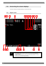
its front panel. The POWER LED lights, and images are displayed.
If the POWER LED fails to light, check the connections again.
To conduct the simplified monitoring of the SDI input signals, use the MONITOR OUT connector.
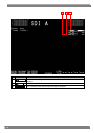
If no input signals are supplied, the image area appears all black, and
NoSignal is displayed in
red on the screen.
* If the setting to display color bars is established when no input signals are supplied, the color bars
will be displayed in the image area.