


Garmin GPSMAP 695/696 Owner’s Manual
190-00919-00 Rev. F
Appendix D
210
OverviewGPS NavigationFlight PlanningHazard AvoidanceAdditional FeaturesAppendicesIndex
EMI
FILTER
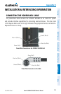
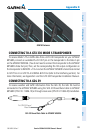
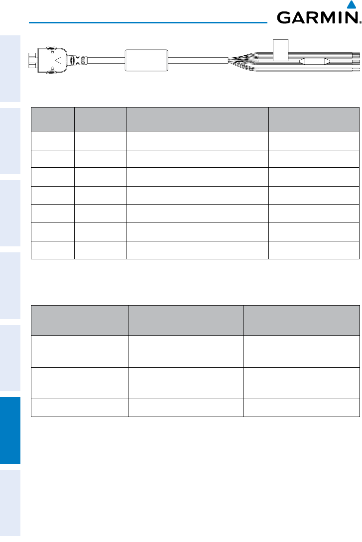
GDL 39 Bare Wire Cable
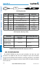
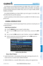
PIN # Direction Description Wire Color
1 IN Voltage Supply Input Red
6 GND Black
10 IN RS-232 RXDA (GDL39 IN) White/Green
11 OUT RS-232 TXDA (GDL39 OUT) Green
12 IN Descrete Input Gray
13 IN RS-232 RXDB (GDL39 IN) White/Orange
14 OUT RS-232 TXDB (GDL39 OUT) Orange
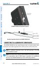
GDL 39 Bare Wire Cable Pinout (18Pin)
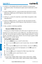
Connection
GPSMAP 695/695 Bare
Wire Color
GDL 39 Bare Wire Color
TX (Data Out) from
GPSMAP 695/696
Blue Wire White/Green Wire
RX (Data In) into
GPSMAP 695/696
Yellow Wire Green Wire
NMEA Out of GLD 39 Orange Wire
GPSMAP 695/696 Aviation Bare Wire Connections to GDL 39
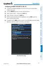
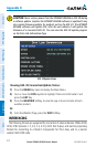
GDL 39 CONFIGURATION
The GPSMAP 695/696 has only one serial connection, but when two serial
connections are needed the GDL 39 can be configured to pass serial information
through the GDL 39 NMEA OUTPUT MODE to a secondary serial device. The GPSMAP
695/696 must also be configured correctly to receive traffic and weather information
from the GDL 39.