


13 - 36
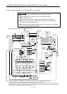
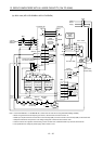
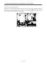
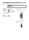
13. SERVO AMPLIFIERS WITH A LARGE CAPACITY (30k TO 55kW)
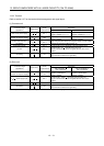
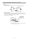
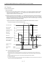
(2) I/O interfaces
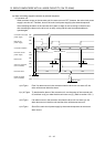
(a) Digital input interface (DI)
Give a signal with a relay or open collector transistor. Refer to section 3.7.3 for the source input.
EM1
Converter unit
Switch
Approx. 5mA
For transistor
DICOM
V
CES
1.0V
I
CEO
100 A
TR
24VDC 10
150mA
5.6k
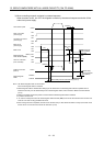
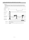
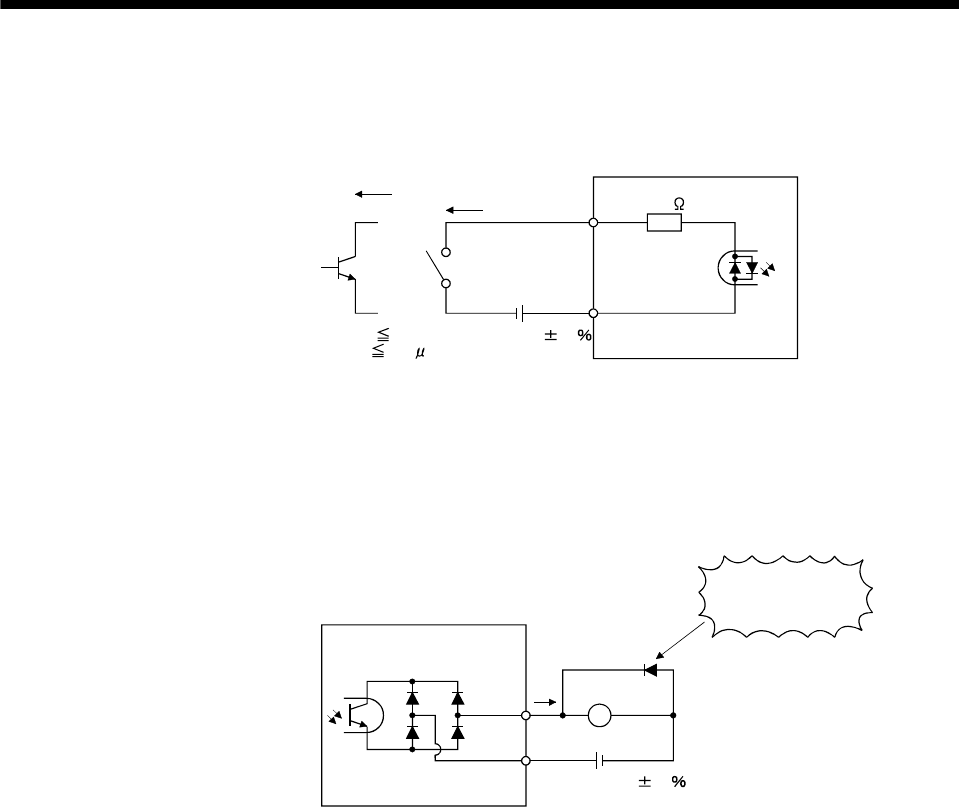
(b) Digital output interface (DO)
A lamp, relay or photocoupler can be driven. Install a diode for an inductive load, or install an inrush
current suppressing resistor for a lamp load. (Permissible current: 40mA or less, inrush current: 100mA
or less) A maximum of 2.6V voltage drop occurs in the servo amplifier.
Refer to section 3.7.3 for the source output.
Converter unit
ALM,
etc.
Load
DOCOM
24VDC 10
150mA
If polarity of diode is
reversed, converter
unit will fail.
(Note)
Note. If the voltage drop (maximum of 2.6V) interferes with the relay operation, apply high
voltage (up to 26.4V) from external source.