


Chapter 6: Peripheral Devices & Accessories
Installation
Psion Teklogix 8515 Vehicle-Mount Computer User Manual 133
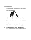
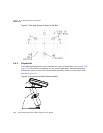
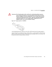
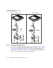
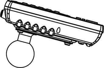
Figure 6.7 Mounting Bracket Attached To The 8515
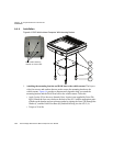
2. Secure the RAM Base to the local platform and attach RAM Standard Arm:
Use the supplied bolt hole pattern to drill the required holes in the local platform.
Hole diameters must not exceed 10mm [13/32 inches]. Hardware (G, H, C, and J)
for securing RAM Bases (B or F) to the local platform are in the recommended
sizes (see Table 6.1 on page 128). If replacement hardware is required, it should be
consistent with these diameters. All fasteners must use a suitable locking mecha-
nism to ensure that they do not loosen under shock and vibration.
• If you are assembling with the RAM Vesa Base, see Section 6.4.4.1:“RAM Vesa
Base”.
• If you are assembling with the RAM Circular Base, see Section 6.4.4.2:“RAM Circu-
lar Base”.
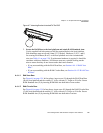
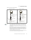
6.4.4.1 RAM Vesa Base
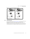
See Figure 6.8 on page 134. In four places, insert screw (G) through the RAM Vesa Base
(B), the local platform and the washer (C). Affix with nut (J). Torque to 26 in-lbs. Secure
RAM Standard Arm (E) by inserting RAM Balls into both ends of arm sockets.
6.4.4.2 RAM Circular Base
See Figure 6.8 on page 134. In four places, insert screw (H) through the RAM Circular Base
(F), the local platform and the washer (C). Affix with nut (J). Torque to 26 in-lbs. Secure
RAM Standard Arm (E) by inserting RAM Balls into both ends of sockets.