


6-28
Chapter 6, COMPUTER OPERATION
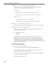
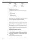
bit number bit negated bit asserted
0 data + parity = 8 bits data + parity = 9 bits
1 no parity bit 1 parity bit
2 even parity odd parity
3 echo disabled echo enabled
4 prompt disabled prompt enabled
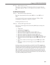
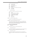
GP [n
1
[n
2
]] Set/read GPIB parameters
n
1
sets the GPIB address in the range 0 to 31
n
2
sets the GPIB terminator and the test echo function according to the following
table:
n Terminator
0 [CR], test echo disabled
1 [CR], test echo enabled
2 [CR,LF], test echo disabled
3 [CR,LF], test echo enabled
4 no terminator, test echo disabled
5 no terminator, test echo enabled
When the test echo is on, every character transmitted or received via the GPIB port is
echoed to the RS232 port. This is provided solely as an aid to program development
and should not be enabled during normal operation of the instrument.
\N n Address command
When the model 7220 is daisy-chained with other compatible instruments this
command will change which instrument is addressed. All daisy-chained instruments
receive commands but only the currently addressed instrument will implement or
respond to the commands. The exception is the \N n command. If n matches the
address set from the front panel the instrument will switch into addressed mode. If n
does not match the address set from the front panel the instrument will switch into
unaddressed mode.
Note: The \N n command does not change the address of an instrument but which
instrument is addressed.
Warning: All instruments must have a unique address.
DD [n] Define delimiter control
The value of n, which can be set to 13 or 32 to 125, determines the ASCII value of
the character sent by the lock-in amplifier to separate two numeric values in a two-
value response, such as that generated by the MP (magnitude and phase) command.
ST Report status byte
Causes the lock-in amplifier to respond with the status byte.
Note: this command is not normally used in GPIB communications, where the status