


5-20
Chapter 5, FRONT PANEL OPERATION
The line filter is disabled; AC coupling is established; the voltage measurement mode
is entered, using the single-ended, A, input; the FET input devices are enabled; the
FLOAT mode is set. If the reference frequency is more than 10 Hz the output time
constant is set to 100 ms, otherwise it is set to the lowest synchronous value; the filter
slope is set to 12 dB/octave; output expand is switched off; the reference harmonic
mode is set to 1; the X offset and Y offset functions are switched off; Auto-Phase and
Auto-Sensitivity functions are called. The Auto-Sensitivity function also adjusts the
AC Gain if required.
The Auto-Measure function is intended to provide a means of setting the instrument’s
controls quickly to conditions which will be approximately correct for typical simple,
single-ended measurement situations. For optimum results in any given situation it
may be convenient to start with an Auto-Measure operation and subsequently fine
tune the setup conditions manually.
The Auto-Measure function is most often used as a rescue operation to bring the
instrument into a well-defined state when it is giving unexpected results. The length of
the above list demonstrates that one or more items can easily be overlooked if
performed manually.
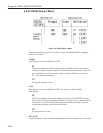
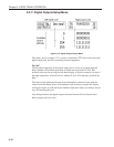
5.4 Main Display Mode - Left-hand LCD
The Main Display Mode is the default mode on instrument power-up. Two controls,
chosen from a possible ten, may be adjusted using the left-hand display, although it is
not possible to show the same control on both lines of the display simultaneously. The
choice of control is made using the SELECT keys adjacent to the left-hand side of
the left-hand display. Once selected, the control is adjusted using the ADJUST keys
adjacent to the right-hand side of the left-hand display.
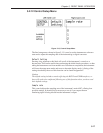
The ten controls are now discussed in turn. Note that in the following figures the
vertical lines below the heading “Left-hand LCD” depict the horizontal limits of the
display to indicate how control information is shown. It should be remembered that
there are two lines available on the display and the user may choose to show a control
on either the upper or the lower line (see figure 4-4).
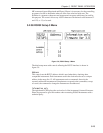
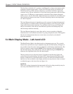
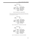
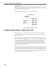
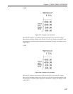
Sensitivity
When set to voltage input mode, the instrument’s full-scale voltage sensitivity may be
set to any value between 20 nV and 1 V in a 1-2-5 sequence.