


3-9
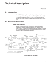
Chapter 3, TECHNICAL DESCRIPTION
3.3.02 Relative Accuracy
The majority of lock-in amplifier measurements are concerned with the variation of
the input signal with time, temperature, etc. or with the comparison of two different
specimens. In these cases the absolute accuracy is of less importance than the
accuracy with which readings can be transferred from range to range.
A new feature of the model 7220 is the introduction of a separate control function
(“AC Gain”) for the gain of the signal channel. Where appropriate, this can be set to
accommodate the existing noise level and subsequent changes in the instrument’s full-
scale sensitivity do not cause any of the errors which might arise from a change in the
analog gain.
3.4 Full-Scale Sensitivity and AC Gain Control
The full-scale sensitivity is indicated as SEN on the left-hand LCD and is adjusted by
the use of the adjacent keys. The analog outputs and analog meter limit at a level a
few percent above the full-scale sensitivity value, but the digital displays do not limit
until a level of ±300 percent full-scale has been reached.
As stated in section 3.2.04, the best performance is obtained by making the AC Gain
value as large as possible without causing amplifier overload.
Note that the demodulator gain is adjusted automatically when the AC Gain value is
changed, in order to maintain the SEN value. However, the user is prevented from
setting an illegal AC Gain value, i.e. one that would result in overload on a full-scale
input signal. Similarly, if the user selects a SEN value which causes the present AC
Gain value to be illegal, the AC Gain will change to the nearest legal value.
In practice, this system is very easy to operate. However, the user may prefer to
make use of the AUTOMATIC AC Gain facility which gives very good results in
most circumstances.
Note that when signal channel overload occurs, the only action required is to reduce
the AC Gain.
At reference frequencies above 1 Hz, the Auto-Sensitivity and Auto-Measure
functions can be used to adjust the full-scale sensitivity.
3.5 Dynamic Reserve
At any given setting, the ratio
DR = 0.7 (INPUT LIMIT) / (FULL-SCALE SENSITIVITY)
represents the factor by which the largest acceptable sinusoidal interference input
exceeds the full-scale sensitivity and is called the Dynamic Reserve of the lock-in
amplifier at that setting. (The factor 0.7 is a peak to rms conversion). The dynamic