


6-4
Chapter 6, COMPUTER OPERATION
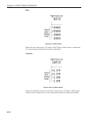
Where the RS232 parameters of the terminal or computer are capable of being set to
any desired value, an arbitrary choice must be made. In the model 7220 the
combination set at the factory is even parity check, 7 data bits, and one stop bit
(fixed) because these are the MS-DOS default.
6.3.06 Auxiliary RS232 Interface
The auxiliary RS232 interface allows up to sixteen model 7220s or a mixture of
compatible instruments to be connected to one serial port on the computer. The first
lock-in amplifier is connected to the computer in the usual way. Additional lock-in
amplifiers are connected in a daisy-chain fashion using null-modem cables, the
AUX RS232 port of the first to the RS232 port of the second, the AUX RS232 port
of the second to the RS232 port of the third, etc. The address of the lock-in amplifier
must be set up from the front panel before any communication takes place. At power-
up the RS232 port of each lock-in amplifier is fully active irrespective of its address.
Since this means that all lock-in amplifiers in the daisy-chain are active on power-up,
the first command must be \N n where n is the address of one of the lock-in
amplifiers. This will deselect all but the addressed lock-in amplifier. When it is
required to communicate with another lock-in amplifier, send a new \N n command
using the relevant address.
Note: When programming in C remember that in order to send the character \ in a
string it is necessary to type in \\.
6.3.07 GPIB Interface - General Features
The GPIB is a parallel digital interface with 8 bidirectional data lines, and 8 further
lines which implement additional control and communication functions.
Communication is through 24-wire cables (including 8 ground connections) with
special-purpose connectors which are constructed in such a way that they can be
stacked on top of one another to enable numerous instruments to be connected in
parallel. By means of internal hardware or software switches, each instrument is set
to a different address on the bus, usually a number in the range 0 to 31. In the model
7220 the address is set using the GPIB SETUP 1 setup menu or by means of the GP
command.
A most important aspect of the GPIB is that its operation is defined in minute detail
by the IEEE-488 standard, usually implemented by highly complicated special-
purpose semiconductor devices that are present in each instrument and communicate
with the instrument’s microprocessor. The existence of this standard greatly simplifies
the problem of programming the bus controller, i.e. the computer, to implement
complex measurement and test systems involving the interaction of numerous
instruments. There are fewer interface parameters to be set than with RS232
communications.
The operation of the GPIB requires the computer to be equipped with special-purpose
hardware, usually in the form of a plug-in card, and associated software which enable
it to act as a bus controller. The control program is written in a high-level language,
usually BASIC or C, containing additional subroutines implemented by software
supplied by the manufacturer of the interface card.