


4-2
Chapter 4, FRONT AND REAR PANELS
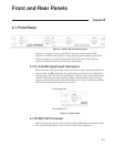
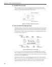
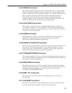
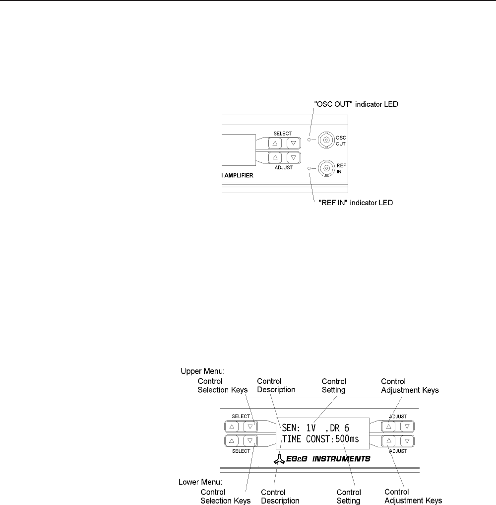
4.1.03 REF IN Connector
This is the input connector for a general purpose external reference signal. When
external reference mode is selected the LED adjacent to the connector will be lit (see
figure 4-3). Under unlock conditions the LED will flash.
Figure 4-3, OSC OUT and REF IN Connectors
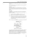
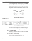
4.1.04 Left-hand LCD Display Panel
This panel and the two pairs of keys on each side of it are normally used to select and
adjust the instrument’s controls, such as the full-scale sensitivity, time constant, filter
slope, oscillator frequency and voltage, etc. In this mode the display shows two of the
possible range of controls and their present settings, one on the upper menu line and
one on the lower (see figure 4-4).
Figure 4-4, Main Display - Left-hand LCD
To select a given control, press the left-hand up or down SELECT keys repeatedly
until it is displayed on the corresponding menu line. The current setting of the control
is then shown adjacent to the description and may be adjusted using the corresponding
left-hand up or down ADJUST keys.
Some controls, such as time constant and full-scale sensitivity, have only a limited
range of settings, and so the use of the ADJUST keys allows the required value to be
chosen with only a few keypresses. Other controls, such as the internal oscillator
amplitude and frequency, may be set over a wide range of values and to a high