


3-2
Chapter 3, TECHNICAL DESCRIPTION
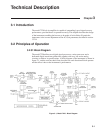
3.2.02 Signal-Channel Inputs
The signal input amplifier may be configured for either single-ended or differential
voltage mode operation, or single-ended current mode operation. In voltage mode a
choice of AC or DC coupling is available and the input may be switched between
FET and bipolar devices. In current mode two conversion gains are selectable to
allow for optimum matching to the signal input. In both modes the input connector
“shells” may be either floated or grounded to the instrument’s chassis ground. These
various features are discussed in the following paragraphs.
Input Connector Selection, A / (A - B)
When set to the A mode, the lock-in amplifier measures the voltage between the
centre and the outer of the A input BNC connector, whereas when set to (A-B) mode
it measures the difference in voltage between the centre pins of the A and B input
connectors.
The latter, differential, mode is often used to eliminate ground loops, although it is
worth noting that at very low signal levels it may be possible to make a substantial
reduction in unwanted offsets by using this mode, with a short-circuit terminator on
the B connector, rather than by simply using the A input mode.
The specification defined as the Common Mode Rejection Ratio, CMRR, defines how
well the instrument rejects common mode signals applied to the A and B inputs when
operating in differential input mode. It is usually given in decibels. Hence a
specification of > 100 dB implies that a common mode signal (i.e. a signal
simultaneously applied to both A and B inputs) of 1 V will give rise to less than
10 µV of signal out of the input amplifier.
Input Connector Shell Ground / Float
The input connector shells may be connected either directly to the instrument’s
chassis ground or they can be “floated” by being connected via a 1 kΩ resistor. When
in the float mode, the presence of this resistor substantially reduces the problems
which often occur in low-level lock-in amplifier measurements due to ground loops.
Input Device Selection, FET / Bipolar
The voltage preamplifier may be switched between bipolar and FET input devices.
The bipolar device, which has an input impedance of 10 kΩ, shows a relatively high
level of added current noise (2 pA/√Hz), but less than 50 percent of the voltage noise
of the FET device. As such, it is intended for use where the source impedance is
resistive or inductive with a resistance of 100 Ω or less, and there is no input voltage
offset.
WARNING: Signal channel overload may occur if the bipolar device is selected
and no DC bias path is provided.
The FET device provides an input impedance of 10 MΩ.
AC / DC Coupling
In normal operation, with reference frequencies above a few hertz, AC coupled
operation is always used.