


Front and Rear Panels
Chapter 4
4-1
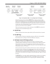
4.1 Front Panel
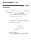
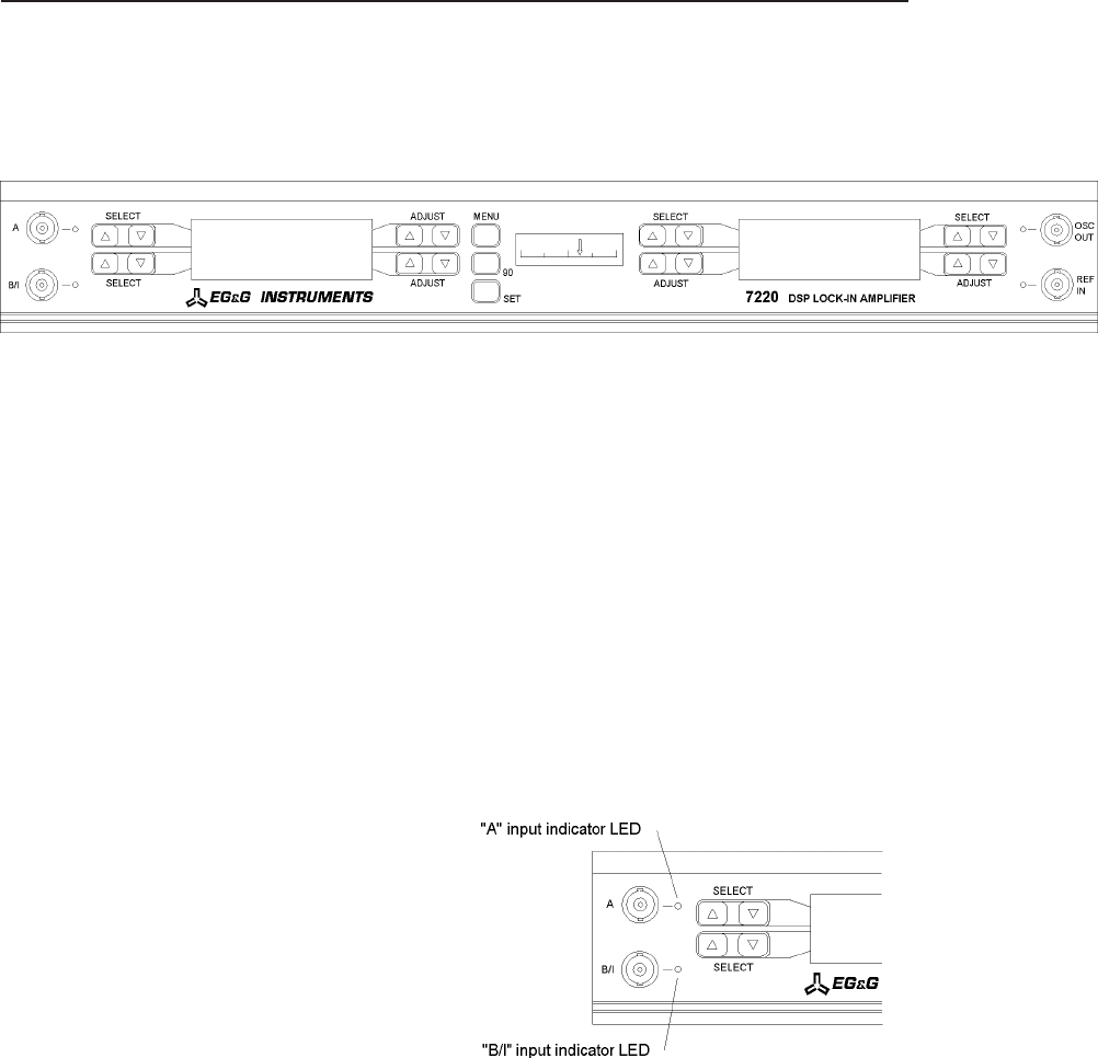
Figure 4-1, Model 7220 Front Panel Layout
As shown in figure 4-1 there are four BNC connectors with associated LED
indicators, two LCD display panels, an edge-indicating analog meter, eight double
and three single keys mounted on the model 7220’s front panel. The following
sections describe the function and location of these items.
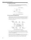
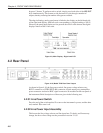
4.1.01 A and B/I Signal Input Connectors
The A connector is the signal input connector for use in single-ended and differential
voltage mode. The B/I connector is the signal input connector for use in differential
voltage mode (A-B) and is also the signal input connector when current input mode is
selected. LEDs adjacent to the connectors light to indicate which of them is active
when a particular input mode is selected (see figure 4-2). One or both of these LEDs
will flash to indicate that the input is in overload.
Figure 4-2, Signal Inputs
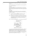
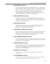
4.1.02 OSC OUT Connector
This is the output connector for the internal oscillator. When internal reference mode
is selected the LED adjacent to the connector will be lit (see figure 4-3).